
Installation Sheet
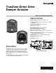
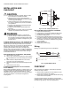
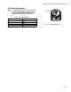

Table Of Contents

TRUEZONE DIRECT DRIVE DAMPER ACTUATOR
33-00038—01 2
INSTALLATION AND
CHECKOUT
CAUTION
1. Read these instructions carefully. Failure to follow
them could cause a hazardous condition.
2. Disconnect power supply before beginning of
installation and wiring of control to prevent electrical
shock or equipment damage.
3. Check the ratings given in the instructions and on
the product to make sure the product is suitable for
your application.
4. All wiring must comply with local electrical codes,
ordinances, and regulations.
5. Installer must be a trained, experienced service
technician.
6. After installation is complete, check out the product
operation as provided in these instructions.
WARNING
1. DO NOT install this actuator on a flue damper.
2. DO NOT attempt to rotate the actuator by turning
the connection coupling or the damper shaft when it
is connected to the actuator or damage to the gear
train may occur.
STANDARD MOUNTING (FOR 5/16” DIA. DAMPER SHAFT)
The M847D can be attached directly to the protruding 5/16”
diameter damper shaft using the sleeve of the output shaft.
Drill a 5/16” (8 mm) hole 1-5/16” (33.5 mm) directly below the
damper shaft opening to accept the anti-rotation shaft
protruding from the base of the motor. The length of the
damper shaft to which the connection coupling is attached is
such as to firmly hold the actuator in a position to adequately
engage the anti-rotation pin in the warm air duct. See Fig. 1
for the critical dimensions.
REPLACING M847D ON A HONEYWELL ARD DAMPER
1. Disconnect the motor wiring.
2. Using a 1/8 in. hex wrench to loosen the motor coupling
from the blade shaft, remove the existing motor assem-
bly.
3. Observe that the damper blades are in the normal,
spring open or spring closed position.
4. Place the new motor onto the shaft and tighten the cou-
pling.
5. Reconnect the motor wiring.
ALTERNATE MOUNTING (FOR 7/16” DIA. COUPLING
STYLE DAMPERS)
Before installing the M847D actuator to a damper with a 7/16”
coupling, insert the drive shaft extension into the drive shaft
and tighten with the set screw provided. See Fig. 2. Also
install the anti-rotation extension to the end of the anti-rotation
rod. Install the actuator on the damper and tighten the
coupling screw.
Fig. 2. For 7/16” Coupling Models Only.
REPLACING M847D ON A HONEYWELL ZD DAMPER
1. Disconnect the motor wiring.
2. Using a 3/16 in. hex wrench to loosen the Allen screw
located above the faceplate at the motor coupling.
3. Remove the existing motor.
4. Observe that the damper blades are in the open posi-
tion with the setscrew pointing toward the damper label.
5. Attach the new motor to the coupling. Make sure that
the standoff on the motor is positioned in the grommet
on the faceplate.
6. Tighten the set screw.
7. Reconnect the motor wiring.
Wiring
See Fig. 3 for typical wiring hook-ups of the M847D.
Fig. 3. Typical M847D Hookup.
CHECKOUT
After completing the installation, check that the equipment
operates correctly as follows:
1. When 24 Vac is applied to the motor leads, the motor
powers to the closed or open position.
2. When power is removed, the motor releases and spring
returns to the normal position.
If full opening and closing is not achieved, check the lower
adjustment lever is to the extreme left and the upper lever is to
the extreme right. See Fig. 4 (Air Flow Adjustments).
M35189
2
1
PROVIDE DISCONNECT MEANS AND OVERLOAD PROTECTION AS REQUIRED.
NOMINAL CURRENT 0.32 AMP.
1
2
24 VAC
60 HZ
ZONING SWITCH
OPERATOR
MOTOR
ORANGE
YELLOW
M35190