
Wiring Guide

6
M1
M4
M6
R
C
W
Y
G
M1
M4
M6
R
C
W
Y
G
M1
M4
M6
R
C
W
Y
G
Rh
Rc
W
Y
G
R
C
DATS
DATS
PURGE OVERRIDE
HZ311
HEAT
COOL
FAN
PURGE
ZONE 1
ZONE 2
ZONE 3
Zone 3
DAMPER
THERMOSTAT
Zone 1
DAMPER
THERMOSTAT
Zone 2
DAMPER
THERMOSTAT
EQUIPMENT
POWERSENSOR
Zone 1 Thermostat
Rc W G
Y
Rh
Power-closed
Spring-open
ARD or ZD Damper
Compressor Relay
Fan Relay
Cooling Transformer
C7735A1000
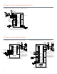
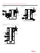
HZ311 zone panel controlling air-conditioning zoned with dampers
and heating zoned with a zone valve or circulator relay panel.
M1
M4
M6
R
C
W
Y
G
M1
M4
M6
R
C
W
Y
G
M1
M4
M6
R
C
W
Y
G
Rh
Rc
W
Y
G
R
C
DATS
DATS
PURGE OVERRIDE
HZ311
HEAT
COOL
FAN
PURGE
ZONE 1
ZONE 2
ZONE 3
Zone 3
DAMPER
THERMOSTAT
Zone 1
DAMPER
THERMOSTAT
Zone 2
DAMPER
THERMOSTAT
EQUIPMENT
POWERSENSOR
ARD or ZD Damper
Wire zones 2 and 3 the
same as zone 1.
Thermostats need to be
configured to energize
fan in heat.
C7735A1000
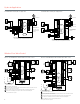
HZ311 zone panel controlling a hydro-air application
* Remove the Rh/Rc jumper on the equipment terminals of the HZ311
Wire zones 2 and 3 the same as zone 1.
The thermostats used must have separate Rh and
Rc (or R and Rc) terminals with jumper removed.
Zone valve or circulator
relay panel
Zone 1
T ( R ) T ( W )
Aquastat
T ( R ) T ( W )
Fan relay center
G Y R
Zone 3 Thermostat
Rc W G
Y
Rh
*
C
R
L1
L2
24 volt transformer
C
R
L1
L2
24 volt transformer
Hydro-air Applications
TrueZONE HZ311 with Hydro-air Application
Wireless Zone Valve Control
A
B
C
D
THM4000R
RH
RC
W1/E
W2
Y1
Y2
G
O
B
DS/BK
HZ322
HEAT 1
HEAT 2
COOL 1
COOL 2
FAN
PURGE
EM HEAT
ZONE 1
ZONE 2
ZONE 3
EMERGENCY
HEAT
M1
M4
M6
R
C
W1/E
W2
Y1
Y2
G
O/B
L
Zone 1
DAMPER
THERMOSTAT
M1
M4
M6
R
C
W1/E
W2
Y1
Y2
G
O/B
L
Zone 2
DAMPER
THERMOSTAT
SENSOR
DATS
DATS
EQUIPMENT
R
C
POWER
M1
M4
M6
R
C
W1/E
W2
Y1
Y2
G
O/B
L
Zone 3
DAMPER
THERMOSTAT
A
B
C
D
WIRELESS
WIRELESS
HOME
CONFIG
CHECK OUT
MODE
BACK NEXT
ADJUST SETTING
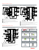
Wireless HZ322 zone panel controlling zone valves.
Transformer
Remove the Rh/Rc jumper at the panel.
C7735A1000
TH TR
End switch
V8043 zone valve
(or equivalent)
Fan center
C
R
If the Honeywell valve has yellow and red wires instead of terminal connections, the red wires are the end switch, the yellow wires
are the TH and TR.
C
G
Y
R
Outdoor
condenser
TH TR
End switch
TH TR
End switch
Wire the end switch from each valve in parallel to the R and W or T and T at the aquastat or boiler.
D
D
C
B
A
A
If cooling is zoned, the dampers (not shown), are wired as normal to the Truezone panel.
B
C
B
B
C
Wireless adaptor*
Parts needed:
1. Wireless Truezone panels: (Verify the box has a Redlink sticker on it)
HZ322K - 3-zones, 2 heat/2 cool.
2. Wireless thermostats with adaptor for zone 1:
Option 1: YTH6320R1023 is a kit that includes a TH6320R wireless programmable thermostat, and
THM4000R1000 wireless adaptor. You would need 1 of these per zone panel.
Option 2:
YTH5320R1025 is a kit that includes a TH5320R wireless non-programmable thermostat, and
THM4000R1000 wireless adaptor. You would need 1 of these per zone panel.
3. Wireless thermostats without adaptor for zones 2-3:
Option 1: TH6320R1004 - Wireless programmable thermostat without adaptor.
Option 2:
TH5320R1002 – Wireless non- programmable thermostat without adaptor.
Accessories: (optional)
REM5000R1001 - Remote Controller (Can control up to 16 thermostats)
C7089R1013 - Wireless Outdoor Sensor.
Aquastat
T(R) T(W)
Wireless TrueZONE HZ322 with Hot Water Zone Valve control
HZ432
HEAT 1
HEAT 2
HEAT 3
COOL 1
COOL 2
PURGE
FAN
EM HEAT
ZONE 1
ZONE 2
ZONE 3
ZONE 4
EMERGENCY
HEAT
M1
M4
M6
R
C
W1/E
W2
W3
Y1
Y2
G
O/B
L
M1
M4
M6
R
C
W1/E
W2
W3
Y1
Y2
G
O/B
L
Zone 3
DAMPER
THERMOSTAT
M1
M4
M6
R
C
W1/E
W2
W3
Y1
Y2
G
O/B
L
Zone 2
DAMPER
THERMOSTAT
M1
M4
M6
R
C
W1/E
W2
W3
Y1
Y2
G
O/B
L
R
C
POWERACCESSORIES
AZ1
AZ2
OT
OT
SENSORS
DATS
DATS
Zone 1
DAMPER
THERMOSTAT
Zone 4
DAMPER
THERMOSTAT
RH
RC
W1/E
W2
W3
Y1
Y2
G
O
B
DS/BK
EQUIPMENT
HOME
CONFIG
CHECK OUT
ADJUST SETTING
A
B
C
D
WIRELESS
A
B
C
D
THM4000R
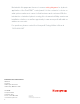
Wireless HZ432 zone panel controlling zone valves.
Transformer
Remove the Rh/Rc jumper at the panel.
Aquastat
T(R) T(W)
C7735A1000
TH TR
End switch
V8043 zone valve
(or equivalent)
Fan center
C
R
If the Honeywell valve has yellow and red wires instead of terminal connections, the red wires are the end switch, the yellow wires are the TH and TR.
C
G
Y
R
Outdoor
condenser
TH TR
End switch
TH TR
End switch
Wire the end switch from each valve in parallel to the R and W or T and T at the aquastat or boiler.
D
D
C
B
A
A
If cooling is zoned, the dampers (not shown), are wired as normal to the Truezone panel.
B
B
C
B
C
Wireless adaptor*
Parts needed:
1. Wireless Truezone panel: (Verify the box has a Redlink sticker on it)
HZ432K - 4-zones, 3 heat/2 cool.
2. Wireless thermostats with adaptor for zone 1:
Option 1: YTH6320R1023 is a kit that includes a TH6320R wireless programmable thermostat, and THM4000R1000 wireless
adaptor. You would need 1 of these per zone panel.
Option 2:
YTH5320R1025 is a kit that includes a TH5320R wireless non-programmable thermostat, and THM4000R1000
wireless adaptor. You would need 1 of these per zone panel.
3. Wireless thermostats without adaptor for zones 2-4:
Option 1: TH6320R1004 - Wireless programmable thermostat without adaptor.
Option 2:
TH5320R1002 – Wireless non- programmable thermostat without adaptor.
Accessories: (optional)
REM5000R1001 - Remote Controller (Can control up to 16 thermostats)
C7089R1013 - Wireless Outdoor Sensor.
E
When a THM4000R is used you cannot expand beyond 4 zones.
E
TH TR
End switch
B
C
Wireless TrueZONE HZ432 with Hot Water Zone Valve control
RH
RC
W1/E
W2
Y1
Y2
G
O
B
DS/BK
HZ322
HEAT 1
HEAT 2
COOL 1
COOL 2
FAN
PURGE
EM HEAT
ZONE 1
ZONE 2
ZONE 3
EMERGENCY
HEAT
M1
M4
M6
R
C
W1/E
W2
Y1
Y2
G
O/B
L
Zone 1
DAMPER
THERMOSTAT
M1
M4
M6
R
C
W1/E
W2
Y1
Y2
G
O/B
L
Zone 2
DAMPER
THERMOSTAT
SENSOR
DATS
DATS
EQUIPMENT
R
C
POWER
M1
M4
M6
R
C
W1/E
W2
Y1
Y2
G
O/B
L
Zone 3
DAMPER
THERMOSTAT
HZ322 zone panel controlling a hydro-air application.
ARD or ZD Damper
Wire zones 2-3 the same
as zone 1.
Zone panel needs to be
configured to energize
fan in heat.
R
C
L1
L2
Transformer
* Remove the Rh/Rc jumper on the equipment terminals of the HZ322
Aquastat
T ( R ) T ( W )
Fan relay
center
G Y R
Zone 3 Thermostat
Rc W G
Y
Rh
*
C7735A1000
TrueZONE HZ322 with Hydro-air Application
Remove the Rh/Rc jumper at the panel.
If the Honeywell valve has yellow and red wires instead of terminal connections, the red wires are the end
switch, the yellow wires are the TH and TR.
Wire the end switch from each valve in parallel to the R and W or T and T at the aquastat or boiler.
If cooling is zoned, the dampers (not shown), are wired as normal to the TrueZONE panel.
See parts needed section on page 7.
D
C
B
A
Remove the Rh/Rc jumper at the panel.
If the Honeywell valve has yellow and red wires instead of terminal connections, the red wires are the end
switch, the yellow wires are the TH and TR.
Wire the end switch from each valve in parallel to the R and W or T and T at the aquastat or boiler.
If cooling is zoned, the dampers (not shown), are wired as normal to the TrueZONE panel.
When a THM4000R is used you cannot expand beyond 4 zones.
See parts needed section on page 7.
D
C
B
A
E