
Wiring Guide

4
Hot Water Zone Valve or Circulator Relay Panel Control
RH
RC
W1/E
W2
Y1
Y2
G
O
B
DS/BK
HZ322
HEAT 1
HEAT 2
COOL 1
COOL 2
FAN
PURGE
EM HEAT
ZONE 1
ZONE 2
ZONE 3
EMERGENCY
HEAT
M1
M4
M6
R
C
W1/E
W2
Y1
Y2
G
O/B
L
Zone 1
DAMPER
THERMOSTAT
M1
M4
M6
R
C
W1/E
W2
Y1
Y2
G
O/B
L
Zone 2
DAMPER
THERMOSTAT
SENSOR
DATS
DATS
EQUIPMENT
R
C
POWER
M1
M4
M6
R
C
W1/E
W2
Y1
Y2
G
O/B
L
Zone 3
DAMPER
THERMOSTAT
Zone 1 Thermostat
Power-closed
Spring-open
ARD or ZD Damper
Wire zones 1-2 the
same as zone 3.
RcWG
Y
Rh
Zone valve or circulator
relay panel
Zone 1
T ( R ) T ( W )
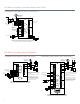
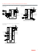
HZ322 zone panel controlling a zone valve or circulator relay panel.
Remove the Rh/Rc jumper on the equipment terminals of the HZ322
C7735A1000
Fan Relay
Compressor Relay
Cooling
Transformer
C
R
L1
L2
24 volt transformer
TrueZONE HZ322 with Hot Water Zone Valve or Circulator Relay Panel
Hot Water Zone Valves with A/C Dampers
There are different ways to wire zone
valves to the aquastat. For complete
wiring instructions on any of the zone
valve and aquastat refer to the product
data sheets for those controls.
M1
M4
M6
R
C
W
Y
G
M1
M4
M6
R
C
W
Y
G
M1
M4
M6
R
C
W
Y
G
Rh
Rc
W
Y
G
R
C
DATS
DATS
PURGE OVERRIDE
HZ311
HEAT
COOL
FAN
PURGE
ZONE 1
ZONE 2
ZONE 3
Zone 3
DAMPER
THERMOSTAT
Zone 1
DAMPER
THERMOSTAT
Zone 2
DAMPER
THERMOSTAT
EQUIPMENT
POWERSENSOR
Zone 1 Thermostat
Rc W G
Y
Rh
Power-closed
Spring-open
ARD or ZD Damper
Th Tr
Wire zones 2 and 3 the same as zone 1.
(Yellow wires)
Compressor Relay
Fan Relay
Cooling Transformer
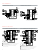
The thermostats used must have separate
Rh andRc (or R and Rc) terminals with
jumper removed.
C7735A1000
HZ311 zone panel controlling air-conditioning zoned with
dampers and heating zoned with hot water zone valves.
V8043 zone valve
24 volt
transformer
C
R
L1
L2
C
R
L1
L2
24 volt
transformer
TrueZONE HZ311 with Hot Water Zone Valves and A/C Dampers
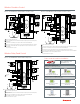
HZ432 zone panel controlling air-conditioning zoned with
dampers and heating zoned with hot water zone valves.
HZ432
HEAT 1
HEAT 2
HEAT 3
COOL 1
COOL 2
PURGE
FAN
EM HEAT
ZONE 1
ZONE 2
ZONE 3
ZONE 4
EMERGENCY
HEAT
M1
M4
M6
R
C
W1/E
W2
W3
Y1
Y2
G
O/B
L
M1
M4
M6
R
C
W1/E
W2
W3
Y1
Y2
G
O/B
L
Zone 3
DAMPER
THERMOSTAT
M1
M4
M6
R
C
W1/E
W2
W3
Y1
Y2
G
O/B
L
Zone 2
DAMPER
THERMOSTAT
M1
M4
M6
R
C
W1/E
W2
W3
Y1
Y2
G
O/B
L
R
C
POWER
ACCESSORIES
AZ1
AZ2
OT
OT
SENSORS
DATS
DATS
Zone 1
DAMPER
THERMOSTAT
Zone 4
DAMPER
THERMOSTAT
RF PORT
RH
RC
W1/E
W2
W3
Y1
Y2
G
O
B
DS/BK
EQUIPMENT
HOME
CONFIG
CHECK OUT
ADJUST SETTING
C7735A1000
Fan Relay
Compressor Relay
Cooling Transformer
Power-closed
Spring-open
ARD or ZD Damper
Zone 1 Thermostat
Rc W G
Y
Rh
Th Tr
(Yellow wires)
V8043 zone valve
*
There are different ways to wire zone
valves to the aquastat. For complete
wiring instructions on any of the zone
valve and aquastat refer to the product
data sheets for those controls.
Wire zones 2 -4 the same as zone 1.
The thermostats used must have separate
Rh and Rc (or R and Rc) terminals with
jumper removed.
C
R
L1
L2
24 volt transformer
C
R
L1
L2
24 volt transformer
TrueZONE HZ432 with Hot Water Zone Valves and A/C Dampers