
Replacement Part Install Instructions
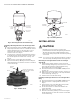
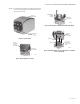

Table Of Contents

40003916-500 SERIES REPLACEMENT POWERHEAD
95C-10944—04 2
Fig. 1. Removing Actuator from Valve Body.
Installing a New-Style Actuator on a New-Style Valve
Body
1. Place the manual lever in the MAN. OPEN position.
2. Align the parallel flat surfaces on double-D shaft of
valve body with notch on side of body (i.e. 90° to
water flow.) This makes the attachment of the
actuator easier. (See Fig. 2)
3. Line up motor coupling to the parallel flat surfaces
in double-D shaft of body and fit the actuator onto
the valve body. Ensure shaft seats correctly. (See
Fig. 3.)
4. Snap actuator onto body by pressing down.
5. Reconnect the wiring. (Wiring connections may be
made either before or after the actuator is installed
on the valve body.)
Fig. 2. Shaft Position.
Fig. 3. Installing Actuator.
INSTALLATION
CAUTION
Normally it is not necessary to remove the
powerhead from the valve body during installation.
The valve must be disassembled with the water
flow arrow pointing away from the manual opening
or lever slot.
NOTE: It is not necessary to drain the hydronic system if
the valve body assembly remains in the pipe line.
Removing an Old-Style Actuator from an Old-Style
Valve Body
1. Switch power supply OFF. Disconnect electrical
leads carefully, noting the position and color of each
lead. (Tip: label the wires indicating where they
belong before disconnecting them.)
2. Place the manual lever in the MAN. OPEN position.
(See Fig. 4.)
3. Remove the covering over the actuator. (See Fig. 5.)
4. Remove the two screws that secure the powerhead
to the valve body. (See Fig. 6.)
5. Lift the actuator off the valve body.
Installing a New-Style Actuator on an Old-Style Valve
Body
1. Place the manual lever in the MAN. OPEN position.
2. Align the actuator coupling with the shaft. (See
Fig. 7.)
3. Snap actuator onto valve body by pressing down.
Ensure that the shaft seats correctly.
4. Secure the actuator on either side with the two
screws provided.
5. Replace the cover over the actuator.
6. Reconnect the wiring. (Wiring connections may be
made either before or after the actuator is installed
on the valve body.)
3a. DEPRESS
LOCKING
BUTTON
3b. LIFT ACTUATOR
STRAIGHT UP
2. PLACE MANUAL
LEVER IN MAN.
OPEN POSITION
AUTO
M32234
OPEN
PARALLEL FLAT SURFACES
ALIGN WITH NOTCH ON SIDE
OF VALVE BODY
DOUBLE-D
SHAFT
NOTCH
M16857
A
CTUATOR
COUPLING
NOTCH
NOTCH TAB
M16859