
Installation Guide


6
Installing 240-volt Circuits
Any two adjacent circuit selector switches may be used for a double-pole 240-volt circuit.
Use a handle tie to connect the two circuit selector switches.
*Note: Circuits used for multi-wire branch circuits are not available for 240-volt
circuits
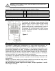
Removing handle tie(s). If there are no 240-volt or multi-wire circuits in the transfer
switch installation, handle-ties on the switches are not needed. To remove a handle tie,
place the handle-tied switches in a position opposite of the other switches. Rotate the
cylindrical spacer between the switches upward repeatedly until the threaded shaft is
exposed on the right switch. Grab the threaded shaft and continue to rotate the spacer
upward until the spacer is free, being carefully not to drop the spacer when it becomes
free. Remove the shaft from the switch. If the shaft is not exposed after several revolution
of the spacer, insert a small slot screwdriver in the hole in the right switch and continue
rotating the spacer upward while the screw driver prevents the shaft from rotating.
Adding handle ties. If additional ties are needed to accommodate additional 240-volt
or multi-wire circuits, they can be added to adjacent pairs of switches.
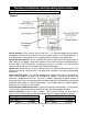
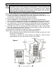
Installing 240-volt circuit(s)
1. Locate the two red and two black wires from any adjacent circuit positions.
2. Turn off the double-pole breaker in the load center.
3. Loosen the screws that secure each wire to each circuit breaker. Disconnect the wires
from the circuit breakers.
4. Feed the two red wires in Step 1 to the double-pole circuit breaker.
5. Cut the red wires to a convenient length. Strip 5/8" from the end of each wire. Connect
the two red wires to the double-pole circuit breaker.
6. Cut the black wires to a length convenient for aligning with wires removed from the
circuit breaker. Strip 5/8" from the end of each wire.
7. Insert one wire removed from the circuit breaker and one black wire into a yellow wire
connector. Twist to tighten and push the wires back into the wiring compartment of the
load center. Do the same for the other wire removed from the circuit breaker and the
other black wire from the transfer switch.
8. Be sure that a handle tie is connected between the two circuit selector switches.
Repeat steps 1-8 for the other double-pole circuits.
30-Ampere Circuits. Only circuits A and B may be used for 30-amp. circuits. Follow the
above wiring instructions for installing 240-volt circuits. If 30-amp. single-pole circuits are
being used, refer to the previous section regarding installation of 120-volt cirucits.
For models with C or D suffix, or to hard wire any cord-connected model, continue to the
next section entitled "Hard-wire Installation" to complete the installation.
For models with a A or B suffix skip to "Inlet Installation for Indoor Models Used Outdoors"
on page 7.
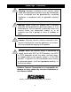
Warning:
Transfer switch circuits with 20 amp breakers must be installed on only
those branch circuits with 20 amp branch circuit breakers. Transfer switch circuits
with 15 amp breakers can be installed on 15 or 20 amp branch circuits. Do not
install any transfer switch circuit on branch circuits greater than 20 amps,
except in position A and B which must be 30 amps.