2006 ST1300/A SET-UP INSTRUCTIONS Set-up and pre-delivery service must be performed by an authorized Honda motorcycle dealer. ©2006 American Honda Motor Co., Inc.
IMPORTANCE OF PROPER SET-UP AND PRE-DELIVERY SERVICE FOR YOUR CUSTOMER'S SAFETY Proper set-up and pre-delivery service are essential to rider safety and the reliability of the machine. Any error or oversight made by the technician assembling and servicing a new machine can result in faulty operation, damage to the machine, or injury to the rider. WARNING Improper set-up or pre-delivery service can create an unsafe condition that can cause your customer to be seriously hurt or killed.
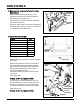
2006 ST1300/A How To Use This Manual Follow the complete sequence of steps as shown. Do not short-cut any steps. The sequence has been established to ensure the unit is properly assembled. The individual steps are composed of three components: • Sub-heading—The large sub-headings are a brief description of the step. They are intended to be used by the experienced technician, one who only needs a brief reminder of the set-up sequence.
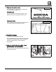
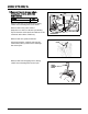
1. Remove the carton cover. STRAP COVERED CRATE The ST1300/A is crated in one of two ways. You may receive either one. Covered crate: Cut the strap and remove the carton cover. Remove the inner cardboard frame cover. Uncovered crate: UNCOVERED CRATE When stacking crates, protect the motorcycle from falling objects and bad weather. 2. Check for damage. Check the unit for hidden damage. If you find damage, follow the instructions on the Delivery and Damage Claims Guidelines wall chart (Reorder No.
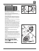
2006 ST1300/A 3. Remove the side braces, wheel, loose parts cartons, and crate frame (cont.). PARTS Riding Tips & Practice Guide FRONT WHEEL CRATE FRAME QTY 1 Remove the bolts and side braces, being careful not to damage the front wheel. SIDE BRACES Remove the loose parts cartons. Keep the You and Your Motorcycle Riding Tips & Practice Guide and hand deliver to the customer at the time of delivery. FRAME BOLTS Remove the nuts, plate, and bolts.
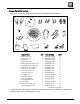
4. Loose Parts Information. Unpack the remaining loose parts and check them against this illustration. 4. 3. 1. 5. 6. 2. 7. 8. 11. 12. 10. 9. 13. 17. 16. 15. 14. DESCRIPTION 1. Right mirror cover Left mirror cover QTY PART NUMBER STEP 1 88111-MCS-G00ZJ 8 1 88121-MCS-G00ZJ 8 2. Windscreen 1 64150-MCS-G00 9 3. Windscreen cover 2 64151-MCS-G00 9 4. Right windscreen bracket cover Left windscreen bracket cover 5. Right mirror cover rubber Left mirror cover rubber 6.
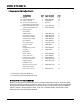
2006 ST1300/A 4. Loose parts information (cont.). DESCRIPTION QTY PART NUMBER STEP 12. Tool kit 1 ------------------------ 12 13. Owner’s Manual bag 1 83642-MN5-000 12 14. Owner’s Manual 1 31MCS630** 12 15. You and Your Motorcycle Riding Tips & Practice Guide 1 G0045*** 3 16.
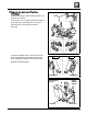
5. Remove the motorcycle from the crate base. Install lifting slings on the engine guards and grab rails as shown. SLINGS If necessary, use a spreader board to prevent the slings from damaging the motorcycle. Lift the slings just enough to remove the slack. Loosen the caliper bolts, axle bolt, and axle pinch bolts. Remove the washer bolts, and lower shipping bracket from the crate base. RIGHT SIDE LEFT SIDE Discard the washer bolts.
2006 ST1300/A 5. Remove the motorcycle from the crate base (cont.). NUTS PROTECTIVE COVERING (discard) Remove the shipping braces, nuts, and protective covering from the foot pegs on both sides of the motorcycle. Lift the motorcycle free from the crate base and remove the base. SHIPPING BRACE On a firm, level surface, lower the centerstand and lower the motorcycle until it is resting on its rear wheel and centerstand. 6. Install the front fender.
7. Install the front wheel. PARTS RIGHT SIDE CALIPER BOLT LEFT SIDE QTY Front wheel assembly 1 Right front wheel side collar 1 Left front wheel side collar 1 Clean both sides of the front and rear brake discs with a clean shop towel and Pro Honda Brake Cleaner or equivalent. 8 x 45 mm CALIPER BOLT CALIPER BOLTS Remove the caliper mounting bolts. Be careful not to get dust and dirt on the ends of the mounting bolts.
2006 ST1300/A 7. Install the front wheel (cont.). Reinstall the right and left front brake calipers, being careful not to damage the front wheel and related components. RIGHT SIDE CALIPER BOLTS Install the caliper bolts and tighten to the specified torque. LEFT SIDE 8 x 45 mm CALIPER BOLT CALIPER BOLT Torque: 31 N·m (3.2 kgf·m, 23 lbf·ft) Operate the front brake and pump the forks several times to seat the axle. Check the brake operation by applying the brake lever and pedal.
7. Install the front wheel (cont.). AXLE Make sure the axle end is flush with the front fork leg outer surface as shown. Tighten the left axle pinch bolts to the specified torque. Torque: 22 N·m (2.2 kgf·m, 16 lbf·ft) PINCH BOLTS On the ST1300A, verify the clearance between the ABS front pulser ring and sensor. SENSOR PULSER RING SENSOR Clearance specification: 0.4 - 1.2 mm (0.02 - 0.05 in) If outside the clearance specification range, recheck the wheel installation. PULSER RING 8.
2006 ST1300/A 8. Install the mirrors (cont.). Align the retaining tabs, located on the ends of the mirror cover rubber, with the indentations on the fairing. Push the end of the retainer strap into the hole in the body. Connect the wiring harness terminals colorto-color: right side wires are colored light blue and white, left side wires are colored orange and white.
9. Install the windscreen. PARTS QTY Windscreen 1 Windscreen cover 2 Right windscreen bracket cover 1 Left windscreen bracket cover 1 Plastic retainer 4 Side cover collar 4 Flange bolt 6 x 18 mm 4 Pan screw 4 x 25 mm 4 Adjuster rubber 2 Note that the windscreen adjusters are installed as shown, however, they can be reinstalled according to rider preference.
2006 ST1300/A 10. Install the handlebar cover and saddlebag lever lock. PARTS 4 x 6.5 mm SPECIAL SCREWS QTY Handlebar cover 1 Special screw 4 x 6.5 mm 2 IGNITION KEY HANDLEBAR COVER Remove the ignition key from the ignition. Remove the protective tape. Attach the handlebar cover using two 4 x 6.5 mm special screws. Torque the screws. Torque: 1.2 N·m (0.12 kgf·m, 0.9 lbf·ft) PROTECTIVE TAPE Open the left fairing pocket with the ignition key.
11. Remove the rear seat. REAR SEAT Insert the ignition key and turn it clockwise to open the latch lever. LATCH LEVER Pull the rear seat back and up while depressing the seat opener. SEAT OPENER 12. Store the tool kit and Owner’s Manual. PARTS QTY Tool kit 1 Owner’s Manual bag 1 Owner’s Manual 1 TOOL BAND TOOL KIT Place the tool kit under the rear seat and secure it with the tool band. Place the Owner’s Manual into its bag and place it on top of the tool kit. OWNER’S MANUAL AND BAG 13.
2006 ST1300/A 14. Install the engine guard covers. PARTS QTY Right engine guard cover 1 Left engine guard cover 1 Pan screw 6 x 11 mm 2 Install the engine guard covers and secure them with a 6 x 11 mm pan screw. Torque the screws. Torque: 9.0 N·m (0.9 kgf·m, 6.6 lbf·ft) 6 x 11 mm PAN SCREW 15. Install the fuel tank knee grip pads. PARTS FUEL TANK QTY Right knee grip pad 1 Left knee grip pad 1 Install the optional knee pads if the customer requests them to be installed.
16. Verify the proper routing of the cables, hoses, and wire harnesses. NEGATIVE (-) CABLE NEGATIVE (-) BATTERY TERMINAL POSITIVE (+) BATTERY TERMINAL BATTERY BOX RIGHT TURN SIGNAL 2P (SKY BLUE) CONNECTOR RIGHT RUNNING LIGHT CONNECTOR LEFT TURN SIGNAL 2P (ORANGE) CONNECTOR LEFT RUNNING LIGHT CONNECTOR ©2006 American Honda Motor Co., Inc.
2006 ST1300/A 17. Service and install the battery. Service the battery only if the unit is sold or will be used as a demonstrator. FRONT SEAT Remove the seats: If the rear seat is installed, follow the instructions for seat removal in step 11. Remove the front seat by pulling it back and up. Remove the right saddlebag: LATCH LEVER Insert the ignition key and turn it clockwise to open the latch lever. Remove the right side saddlebag by lifting up and pulling it out. Close the latch lever.
17. Service and install the battery (cont.). Remove the battery cover. Remove the battery holder by removing the bolt. NUTS AND BOLTS CAP Pull the battery out of the battery box. Remove the cap and the packed battery nuts and bolts. The battery in this motorcycle is a precharged, maintenance-free type. The electrolyte has been added at the factory. BATTERY Follow the instructions included in Service Letter #48. Make sure the ignition switch is in the OFF position.
2006 ST1300/A 17. Service and install the battery (cont.). Reinstall the front seat: Insert the seat prong under the tank and align the two recesses with the prongs at the rear of the tank. Make sure that the seat adjustment guides align with the holes in the seat and push down on the rear of the seat to secure it into position. HOLES FRONT SEAT RECESSES PRONG Reinstall the rear seat: Reinstall the rear seat by following the instructions in step 13.
18. Check the coolant level. Check the coolant level at the coolant reserve tank. If the level is low, remove the coolant reserve tank cap and add Pro Honda HP coolant or a 1:1 mixture of a high-quality ethylene glycol anti-freeze containing corrosion inhibitors and distilled water to restore the level to the UPPER mark. Do not spill coolant on painted or plastic surfaces as it can damage the finish. UPPER LEVEL MARK RESERVE TANK RESERVE TANK CAP LOWER LEVEL MARK 19. Verify the throttle freeplay.
2006 ST1300/A 20. Check the oil level (cont.). If the oil level is below the lower level mark, remove the right cylinder head over-head cover and oil filler cap, and add the recommended oil until it is visible in the inspection window. Replace the oil filler cap. FILLER CAP Start the engine and let it idle for 3 – 5 minutes. Make sure the low oil pressure indicator goes off. If the indicator remains on, stop the engine and troubleshoot the cause. Stop the engine and wait 2 – 3 minutes.
22. Check the front and rear brake reservoir fluid levels. FRONT BRAKE SCREWS Turn the handlebar so the front brake reservoir is level and check the fluid level. LOWER LEVEL MARK Support the motorcycle in an upright position on a firm, level surface and check the rear brake fluid level. UPPER LEVEL MARK REAR BRAKE If the fluid level is low in either reservoir, remove the screws, reservoir cover, and diaphragm or cap.
2006 ST1300/A 24. Check the tire pressure. Front and rear: 42 psi. 25. Check the clutch lever and sidestand ignition cut-off switches. When the transmission is in gear, the starter should not work unless the clutch lever is pulled in and the sidestand is up. Position the motorcycle securely with the rear wheel raised off the ground. Clutch lever ignition cut-off switch test: Shift the transmission into gear.
. Adjust the front seat height. The front seat height of the ST1300/A can be adjusted for rider preference. SEAT HEIGHT ADJUSTER Remove the rear seat by referring to the instructions in step 11. Remove the front seat by following the instructions in step 17. Move the seat height adjuster into one of the three positions on the guide as shown. Be sure to align the holes in the rear of the front seat with the adjuster when installing the seat.
2006 ST1300/A Wiring Diagram - ST1300 24 ©2006 American Honda Motor Co., Inc.
Wiring Diagram - ST1300A ©2006 American Honda Motor Co., Inc.