COMPANY CONFIDENTIAL 3GPP Long Term Evolution Cat4 PCI Express M.2 Module Engineering Requirements Specification Project code: T77W595.00 Solution: MDM9625+WTR1625L SKU: WW-1-S3 Copyright © 2014. Foxconn Communications Inc. All rights reserved.
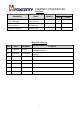
COMPANY CONFIDENTIAL Reviewers Department Name Signature Project Manager Choro.Chung Project Leader Ai-ning Song Hardware Engineer Shao-you Lin Review Dates * Plan ** Results Modification History Rev Date Originator D0.1 2014/07/26 Ai-ning D0.
COMPANY CONFIDENTIAL CONTENTS 1. GENERAL DESCRIPTION ......................................................................4 1.1 SYSTEM MAIN FEATURE ......................................................................5 1.2 SYSTEM BLOCK DIAGRAM ..................................................................9 1.3 PIN DEFINITION .....................................................................................10 1.4 PLATFORM CONNECTION DESIGN .................................................
COMPANY CONFIDENTIAL 1. General Description T77W595.00 is designed to enable wireless data connectivity for notebook computer or any other device compatible with the PCI Express M.2 Specification 3042 type slot. T77W595.00 is the data card solution that delivers wireless wide-area network (WWAN) connectivity for the LTE, UMTS (HSDPA/HSUPA/HSPA+/DC-HSPA+), CDMA 1xRTT/ EV-DOr0/ EV-DOrA / EV-DOrB, GPRS/EDGE and GPS/Glonass protocols in one hardware configuration.
COMPANY CONFIDENTIAL 1.1 System Main Feature Feature Physical Electrical Dimension Shielding design Weight USIM Operating Bands Diversity/2nd Rx GNSS Description PCI express M.2 module, size 3042, 75Pin golden finger Single VCC supply (3.135V~4.4V follow M.2 standard) Dimensions (L × W × H): 42 mm × 30 mm × 2.3 mm, maximum height=2.38mm (add PCB tolerance=0.08mm) Shield case on board design, no additional shielding requirement Approximately 6.
COMPANY CONFIDENTIAL USIM Voltage Support 1.8V and 2.85V, and auto detects follow SIM card type Antenna connectors MAIN and AUX(supports Diversity and GPS simultaneously) Throughput GPRS: DL 85.6 kbps /UL 85.6 kbps EDGE: DL 236.8 kbps/UL 236.8 kbps WCDMA CS: DL 64 kbps /UL 64 kbps WCDMA PS: DL 384 kbps /UL 384 kbps HSPA+: DL 21.6 Mbps /UL 5.76 Mbps DC-HSPA+ :DL 42 Mbps/UL 5.76 Mbps CDMA 1x: DL 153.6 kbps/UL 153.6 kbps EVDO Rev.A: DL 3.1 Mbps /UL 1.8 Mbps EVDO Rev.B: DL 14.7 Mbps/UL 5.
COMPANY CONFIDENTIAL 153.6 kbps forward link, 153.6 kbps reverse link 1xEV-DOr0 High-speed peak data rates – 2.4 Mbps forward link; 153 kbps reverse link 1xEV-DOrA High-speed peak data rates – 3.1 Mbps forward link; 1.8 Mbps reverse link 1xEV-DOrB High-speed peak data rates – 14.7 Mbps forward link; 5.4 Mbps reverse link GSM / GPRS / EDGE air interface R99 Circuit-switched data: 9.6 k; 14.
COMPANY CONFIDENTIAL engine, resulting in an expanded area of coverage over traditional GPS receivers 8
COMPANY CONFIDENTIAL 1.
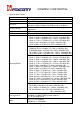
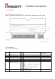
COMPANY CONFIDENTIAL 1.3 Pin definition 1.3.1 Golden finger Pin sequence Figure 1-2 shows the sequence of pins on the 75-pin signal interface of M.2 3042. 1.3.2 Pin definition Table 1-1 M.2 Pin definition No. M.2 Pin name I/O Description 1 2 3 4 5 6 CONFIG_3 3.3V GND 3.3V GND Full_Card_Power_Off (0/1.8V or 0/3.3V) O PI PI PI PI I 7 USB_D+ IO Connected to Ground internally. Power supply (3.1V-4.4V) Ground Power supply (3.3V+/-5%) Ground When it is Low, M.2 card powers off. When it is High, M.
COMPANY CONFIDENTIAL 8 W_DISABLE#1 (0/3.3V) I 9 USB_D- IO 10 LED#1 O 11 GND 12~19 Notch 20 AUDIO_0 PI - 21 CONFIG_0 O 22 AUDIO_1 - 23 WoWWAN (0/1.8V) O 24 AUDIO_2 - 25 DPR (0/1.8V) I 26 W_DISABLE#2 I 27 28 GND AUDIO_3 PI - 29 SSIC-TxN - 30 31 UIM-RESET SSIC-TxP O - 32 33 34 35 UIM-CLK GND UIM-DATA SSIC-RxN O PI IO - 36 UIM-PWR O Active low signal used by the host to turn on/off radio operation. When it is Low, radio off. When it is High, radio on.
COMPANY CONFIDENTIAL 37 SSIC-RxP - 38 N/C - 39 40 GND PI GNSS_SCL (0/1.8V*) IO 41 NC - 42 IO 43 GNSS_SDA (0/1.8V*) NC 44 GNSS_IRQ (0/1.8V*) IO 45 46 GND SYSCLK (0/1.8V*) PI O 47 NC - 48 49 TX_BLANKING NC I - 50 51 52 53 54 55 56 57 58 59 NC GND Reserve Reserve Reserve Reserve Reserve GND Reserve ANTCTL0 (0/1.8V) PI PI O 60 COEX3 (0/1.8V) IO 61 ANTCTL1 (0/1.8V) O 62 COEX2 (0/1.8V) IO 63 ANTCTL2 (0/1.8V) O 64 COEX1 (0/1.
COMPANY CONFIDENTIAL 65 ANTCTL3 (0/1.8V) O 66 67 68 SIM Detect Reset# (0/1.8V) SUSCLK(32kHz) (0/3.3V) CONFIG_1 3.3Vaux GND 3.3Vaux GND 3.3Vaux CONFIG_2 I I - LTE_ACTIVE Tunable antenna control signal, bit 3 SIM_SWP System reset Reserve O PI PI PI PI PI O Connected to Ground internally. Power supply (3.3V+/-5%) Ground Power supply (3.3V+/-5%) Ground Power supply (3.3V+/-5%) Connected to Ground internally.
COMPANY CONFIDENTIAL 1.4 Platform connection design 1.4.1 Configuration Pins The M.2 module provides 4 configuration pins. T77W595 is configured as WWAN-SSIC 0, refer to PCIe M.2_Rev 1.0. Item Module configuration decodes Module type Port configuration Config Config_0 Config_1 Config_2 Config_3 Pin No. 21 69 75 1 WWAN-SSIC 0 State NC GND GND GND 1.4.2 Power and ground (1) Power Rail Parameters Parameter Min Type Max Operating voltage 3.135 3.3 4.4 The operating voltage was defined in PCIe M.2_Rev 1.
COMPANY CONFIDENTIAL 1.4.3 Full_Card_Power_Off The M.2 LTE module can be controlled to power on/off by the Full_Card_Power_Of pin. Item State M.2 card state 1 Low Powers off, It’s internally pulled down by 100K ohm resistor 2 High Powers on, it is 3.3V tolerant but can be driven by either 1.8V or 3.3V GPIO. The recommended connections as below 1.4.4 USB interface T77W595 module is compliant with USB2.0 in all three modes (Low speed, Full speed, and high speed).
COMPANY CONFIDENTIAL 1.4.5 W_DISABLE# This control setting is implementation-specific and represents the collective intention of the host software to manage radio operation. T77W595 provides a hardware pin (W_DISABLE#) to disable or enable the radio. Besides, the radio can also be enabled or disabled through software AT commands.
COMPANY CONFIDENTIAL 1.4.7 WoWWAN The WAKE_ON_WWAN# signal is for power saving. •LTE module always listening at very low power in idle mode •LTE module will wake up mother board via ‘WoWWAN’ signal. •The platform will power on when triggered by the LTE module. The WAKE_ON_WWAN# signal is used to wake up the host. It is open drain and should be pulled up at the host side. When the WWAN needs to wake up the host, it will output a one second low pulse, shown in Figure 1-4-6.
COMPANY CONFIDENTIAL 1.4.8 DPR (Dynamic Power Reduction) The optional DPR signal is used by wireless devices to assist in meeting regulatory SAR (Specific Absorption Rate) requirements for RF exposure. The signal is provided by a host system proximity sensor to the wireless device to provide an input trigger causing a reduction in the radio transmit output power.
COMPANY CONFIDENTIAL 1.4.9 USIM The UIM contains parameters necessary for the WWAN device’s operation in a wireless wide area network radio environment. The UIM signals are described in the following paragraphs for M.2 add-in cards that support the off-card UIM interface. (1) USIM card socket It is recommended to take electrostatic discharge (ESD) protection measures near the USIM card socket.
COMPANY CONFIDENTIAL 1.4.10 Antenna Control T77W595 provides GPIO control signals for external antenna tuner application. The function is under development for customization. ANTCTRL (0-3) are provided to allow for the implementation of antenna tuning solutions. The number antenna control lines required will depend on the application and antenna/band requirements. Foxconn general design for WWAN module with two control signals.
COMPANY CONFIDENTIAL 1.4.12 RESET# Asynchronous RESET# pin, active low. Whenever this pin is active, the modem will immediately be placed in a Power On reset condition. Care should be taken not to activate this pin unless there is a critical failure and all other methods of regaining control and/or communication with the WWAN sub-system have failed. The Reset# signal is relatively sensitive, it is recommended to install one capacitor (10~100pF) near to the M.2 card pin.
COMPANY CONFIDENTIAL 2. Hardware features T77W595.00 consists of the following key engine components, in addition to the required front-end RF and other discrete components. Modem engine ■ Soft Baseband: MDM-9625 ■ RF: WTR1625L ■ Power: PM8019 Connectivity engine ■ USB: USB2.0 high-speed ■ USIM: located off board ■ Antenna: connectors for the off board antennas 2.
COMPANY CONFIDENTIAL ❒ Connectivity: - USB 2.0 HS with built-in USB PHY - UART interface - UIM support (dual voltage) 2.2 RF transceiver The WTR1625L device is a highly integrated and versatile RF CMOS transceiver IC that can be used in multimode, multiband applications – including Rx diversity. The WTR1605 IC is the RF transceiver IC within compatible Qualcomm MDM9625 chipsets. The WTR1625 IC integrates advanced receive and transmit features into a 5.47 × 5.47 × 0.
COMPANY CONFIDENTIAL 2.4 Antenna Design 2.4.1 Antenna specification T77W595.00 also provides connectivity for off board antennas. The antennas and their connection interface for this device satisfy the requirements specified in the PCI Express M.2 Specification Revision Version 1.0 standard. The antenna elements are typically integrated into the notebook/ultrabook /tablet and connected to T77W595.00 module via flexible RF coaxial cables. T77W595.
COMPANY CONFIDENTIAL Figure 2-2 RF connectors 25
COMPANY CONFIDENTIAL Figure 2-3 RF receptacles 26
COMPANY CONFIDENTIAL 3. Mechanical Specifications 3.1 Overview T77W595.00 is compatible with the PCI Express M.2 Specification 3042 type 75-pin card edge-type connector. Refer to Electromechanical Specification Revision 0.7a, Version 1.0 with Input Power and Voltage Tolerance ECN for more details. 3.2 Mechanical constraints Figure 3-1 shows the mechanical constraints of T77W595.
COMPANY CONFIDENTIAL 3.3 M.2 card assembly Figure 3-2 shows Stack-up Mid-Line (In-line) Single Sided Module for 1.5 Maximum Component Height, refer to section 2.4.8.3.1 of PCIe M.2_Rev 1.0 standard. Remark: a. 2.4mm maximum above mother board b. Cut area of main board under M.2 module c. Need to add thermal pad between M.2 module and mechanical component (like material shielding) for thermal dissipation.
COMPANY CONFIDENTIAL 3.4 Connector assembly a. Mate the connector vertically as much as possible. Adjusting the mating axis of plug and receptacle. Do not slant mate. . b. Unmating: In case of unmating by pulling tool. Use the pulling tool as the following drawing, and pull plug to vertical direction as directly as possible c.
COMPANY CONFIDENTIAL 4. Electrical Specifications 4.1 Recommended operating conditions Table 4-1 Recommended operating conditions Parameter Storage temperature Recommend operating temperature (3GPP compliant) Extend operating temperature (operational, non-3GPP compliant) Operating voltage Min -30 -10 Type +25 +25 Max +85 +60 Units °C °C -20 +25 +70 °C 3.135 3.3 4.4 Vdc Operating T77W595.00 device under conditions beyond its absolute maximum ratings (Table 4-1) may damage the device.
COMPANY CONFIDENTIAL 5. RF performance specifications Radio performance for T77W595.00 is given in the following sections, including RF receiver, RF transmitter. 5.1 RF maximum Tx power specifications Table 5-1 Maximum transmit power Mode LTE WCDMA CDMA GPRS E-GPRS Band 1,2/25,3,4,5/26, 7,8,13,12/17,20,28 1,2,4,5,8 BC0,BC1,BC10 1800,1900 850,900 1800,1900 850,900 Class 3 3 3 1 4 E2 E2 3GPP Standard 23+/-2 24+1.7/-3.7 23~30 30+/-3 33+/-3 26+/-3 27+/-3 Design Spec. MFG Spec. 23+/-1 23+2/-1 23.
COMPANY CONFIDENTIAL 5.2 RF min. Rx sensitivity specifications Table 5-2 Conducted min. receiver sensitivity LTE Band (10MHz BW) 1 2 3 4 5 7 8 12 13 17 20 25 26 28 WCDMA 1 2 4 5 8 GPRS / E-GPRS GPRS 1800,1900 GPRS 850,900 EDGE 1800,1900 EDGE 850,900 CDMA BC0 BC1 BC10 GPS/GLONASS tracking sensitivity 3GPP (Combined) -97dBm -95dBm -94dBm -97dBm -95dBm -95dBm -94dBm -94dBm -94dBm -94dBm -94dBm -93.5dBm -94.5dBm -95.5dBm 3GPP (Combined) -106.7dBm -104.7dBm -106.7dBm -104.7dBm -103.
COMPANY CONFIDENTIAL 6. Software Features 6.1 USB Enumeration When a USB device is attached to or removed from the USB, the host uses a process known as bus enumeration to identify and manage the device state changes necessary. When a USB device is attached to a powered port, the following actions are taken: 1. 2. 3. 4. 5. 6. The hub to which the USB device is now attached informs the host of the event via a reply on its status change pipe.
COMPANY CONFIDENTIAL visible to the USB and the host, while others are internal to the USB device. Figure 6-1.
COMPANY CONFIDENTIAL Table 6-1. Visible Device States Attached Powered Default Address Configured Suspended State No -----Device is not attached to the USB. Other attributes are not significant. Yes No ----Device is attached to the USB, but is not powered. Other attributes are not significant. Yes Yes No ---Device is attached to the USB and powered, but has not been reset. Yes Yes Yes No --Device is attached to the USB and powered and has been reset, but has not been assigned a unique address.
COMPANY CONFIDENTIAL activity for 3 ms. It may also have a unique address and be configured for use. However, because the device is suspended, the host may not use the device's function. 6.2 Windows Morphing The device presents itself as different functions on different Windows OS. On windows 7, its functions include Diag, RmNet, Modem, Application Interface and NEMA after the user installs the driver package. On windows 8.1, its functions are MBIM and GPS after the user installs the driver package.
COMPANY CONFIDENTIAL NMEA NMEA Goals of the solution In Windows 7, host sends SET_CONFIGURATION request with value 1 to MDM9625 device. The functions defined in Configuration 1 will be exposed to the host. In Linux, host sends SET_CONFIGURATION request with value 2 to MDM9625 device. The functions defined in Configuration 2 will be exposed to the host In Windows 8, host sends SET_CONFIGURATION request with value 3 to MDM9625 device.
Federal Communication Commission Interference Statement This device complies with Part 15 of the FCC Rules. Operation is subject to the following two conditions: (1) This device may not cause harmful interference, and (2) this device must accept any interference received, including interference that may cause undesired operation. This equipment has been tested and found to comply with the limits for a Class B digital device, pursuant to Part 15 of the FCC Rules.
Radiation Exposure Statement: The product comply with the FCC portable RF exposure limit set forth for an uncontrolled environment and are safe for intended operation as described in this manual. The further RF exposure reduction can be achieved if the product can be kept as far as possible from the user body or set the device to lower output power if such function is available. This device is intended only for OEM integrators under the following conditions: 1. Antennas must be installed at least 2.
product which integrates this module. The end user manual shall include all required regulatory information/warning as show in this manual. Industry Canada statement: This device complies with RSS-210 of the Industry Canada Rules. Operation is subject to the following two conditions: (1) This device may not cause harmful interference, and (2) this device must accept any interference received, including interference that may cause undesired operation.
in the certification filing) must be sued for portable product. Other antenna(s) even with the same antenna type and gain will need a class II permissive to verify the SAR compliance. 3. No co-transmission with other transmitter. As long as 3 conditions above are met, further transmitter test will not be required.
sera chargé de réévaluer le produit final (y compris l'émetteur) et l'obtention d'une autorisation distincte au Canada. End Product Labeling The product can be kept as far as possible from the user body or set the device to lower output power if such function is available. The final end product must be labeled in a visible area with the following: “Contains IC: 2878D-T77W595”.
power (e.i.r.p.) is not more than that necessary for successful communication. This radio transmitter (IC: 2878D-T77W595/ Model: T77W595) has been approved by Industry Canada to operate with the antenna type, maximum permissible gain and required antenna impedance for each antenna type indicated. Antenna types not included in this user's manual, having a gain greater than the maximum gain indicated for that type, are strictly prohibited for use with this device.