
User's Manual

COMPANY CONFIDENTIAL
7
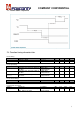
2.1 Host interface characteristics
I
2
C-bus Interface
The I
2
C-bus Interface implements a slave I
2
C-bus interface with integrated shift register, shift timing generation
and slave address recognition.
I
2
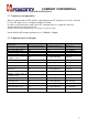
C-bus Standard mode (100 KHz SCL), Fast mode (400 KHz SCL) and High-speed mode (3.4 MHz SCL) are
supported.
I
2
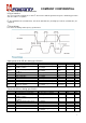
C-bus timings
Here below are timings and frequency specifications.
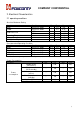
High-speed mode I2C-bus timing specification
Symbol Parameter Conditions Min Max Unit
f
CLK(HIF4)
Clock frequency on pin HIF4 I
2
C-bus SCL; C
b
<100pF 0 3.4 MHz
t
SU;STA
Set-up time for a repeated
START condition
C
b
<100pF 160 - ns
t
HD;STA
Hold time(repeated) START
condition
C
b
<100pF 160 - ns
t
LOW
LOW period of the SCL clock C
b
<100pF 160 - ns
t
HIGH
HIGH period of the SCL clock C
b
<100pF 60 - ns
t
SU;DAT
Date set-up time C
b
<100pF 10 - ns
t
HD;DAT
Data hold time C
b
<100pF 0 - ns
t
r(HIF3)
Rise time on pin HIF3 I
2
C-bus SDA; C
b
<100pF 10 80 ns
t
f(HIF3)
Fall time on pin HIF3 I
2
C-bus SDA; C
b
<100pF 10 80 ns
V
hys
Hysteresis voltage
Schmitt trigger inputs;
C
b
<100pF
0.1*V
PVDD
- V
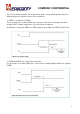
Fast mode I2C-bus timing specification
Symbol Parameter Conditions Min Max Unit
f
CLK(HIF4)
Clock frequency on pin HIF4 I
2
C-bus SCL; C
b
<400pF 0 400 KHz
t
SU;STA
Set-up time for a repeated
START condition
C
b
<400pF 600 - ns
t
HD;STA
Hold time(repeated) START
condition
C
b
<400pF 600 - ns
t
LOW
LOW period of the SCL clock C
b
<400pF 1.3 - ns
t
HIGH
HIGH period of the SCL clock C
b
<400pF 600 - ns
t
SU;DAT
Date set-up time C
b
<400pF 100 - ns
t
HD;DAT
Data hold time C
b
<400pF 0 900 ns
V
hys
Hysteresis voltage Schmitt trigger inputs;
C
b
<400pF
0.1* V
PVDD
- V