COMPANY CONFIDENTIAL Revision Note NFC (Near Field Communication) NXP NPC300 Module Project Name Document Rev. FOXCONN Part No. Module Rev. FRU Part No. Customer Part No. FOXCONN Label Rev NFC (NXP NPC300) Module 5.0 T77H747.10 005 01AX745 SW10K97523 00S0 Prepared by Reviewed by Approved by Bandy.Jiang Wei.
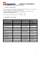
COMPANY CONFIDENTIAL Revision History Revision 1.0 2.0 3.0 4.0 5.0 Date Originator Comment 2016/01/28 Smile. Ming Initial release 1> Add pin 1 marking for mechanical drawing. 2> Add SM bus support in addition to I2C bus. (in page 4,5) 3> Add description of pin9 (TX_PWR_REQ) signal with active high 1.8V level output. (in page 15) 4> Change the PN of antenna connector from BM05B-ACHSS-A-GAN-ETF(LF)(SN) to BM05B2016/04/20 Bandy.Jiang ACHKS-A-GAN-ETF(HF) 5> Update material in shielding drawing.
COMPANY CONFIDENTIAL Content 1. INTRODUCTION ............................................................................................................................................................. 4 1.1 SCOPE ....................................................................................................................................................................... 4 1.2 FUNCTION..................................................................................................................
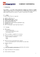
COMPANY CONFIDENTIAL 1. Introduction The T77H747.10 is an NFC module designed for integration in computer or portable equipment and consumer devices compliant with NFC standards (NFC Forum, NCI, ISO/IEC 14443 and ISO/IEC 15693) etc. This module is based on NXP NPC300 solution, which is a highly integrated transmission module for contactless communication at 13.56MHz. 1.1 Scope The NFC module RF protocols supported: 1.2 NFCIP-1, NFCIP-2 protocol NFC Forum device 1.
COMPANY CONFIDENTIAL 1.3 Hardware block diagram The T77H747.10 NFC module is based on NXP NPC300 solution with includes ARM microcontroller core, EEPROM, demodulator and decoder, power management unit, host interface. This module is powered from the host (5V) and interfaces to the host with I2C -bus compatible signals, on-board 27.12 MHz XTAL. Also includes on board low profile FPC/FFC 12pin connector for host interface and 5pin WTB antenna connector for antenna interface. Form factor: 20.0mm x13.0mm x 2.
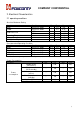
COMPANY CONFIDENTIAL 2. Electrical Characteristics 2.1 operating conditions Absolute Maximum Rating Symbol VBAT PVDD Condition Respect to GND Respect to GND HBM CDM ---- Min. ----0 -20 0 Typ. 5.0 3.3 --+25 +25 -- Max 6.0 4.35 +/-1.0 +/-500 +70 +85 +85 Unit V V KV V ℃ ℃ % Recommended Operating Condition Symbol Condition VBAT Respect to GND PVDD Respect to GND PMUVCC Respect to GND VDD Respect to GND VDD(SIM) Respect to GND Min. 4.5 3.0 1.62 1.65 1.62 Typ. 5.0 3.3 1.8 1.8 1.8 Max 5.5 3.6 1.98 1.95 1.
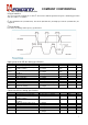
COMPANY CONFIDENTIAL 2.1 Host interface characteristics I2C-bus Interface 2 2 The I C-bus Interface implements a slave I C-bus interface with integrated shift register, shift timing generation and slave address recognition. 2 I C-bus Standard mode (100 KHz SCL), Fast mode (400 KHz SCL) and High-speed mode (3.4 MHz SCL) are supported. I2C-bus timings Here below are timings and frequency specifications.
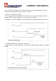
COMPANY CONFIDENTIAL 2.2 Power-up sequence There are 2 different supplies for module which allows set up independently, therefore different power-up sequences have to be considered. 1> VBAT is set up before PVDD This is at least the case when VBAT pin is directly connected to the battery and when module VBAT is always supplied as soon the system is supplied. As VEN pin is referred to VBAT pin, VEN voltage shall go high after VBAT has been set.
COMPANY CONFIDENTIAL 2.3 Power-down sequence 2.
COMPANY CONFIDENTIAL 3. NFC contactless standard conformance 3.1 Frequency interoperability When in communication, NFC module is generating some RF frequencies. It is also sensitive to some RF signals as it is looking from data in the field. In order to avoid interference with others RF communication, it is required to tune the antenna matching for antenna board. (Remark: The antenna matching tuning is responsible for antenna vendor) It must limit the RF frequency dispersion to 13.56MHz +/-50ppm. 3.
COMPANY CONFIDENTIAL 3.3 Contactless interface unit The NFC module supports various communication modes at different transfer speeds and modulation schemes. The following chapters give more detailed overview of selected communication modes. 1> Reader/Writer communication modes Generally 5 reader/writer communication modes are supported: PCD reader/writer for ISO/IEC 14443A/MIFARE The transfer speed includes 106 kbit/s, 212 kbit/s, 424 kbit/s and 848 kbit/s.
COMPANY CONFIDENTIAL 4. Mechanical Architecture 4.1 Module Mechanical Drawing Dimension (WxL): 20mm x 13mm, Module Max Thickness: 2.
COMPANY CONFIDENTIAL 4.2 Antenna interface of NFC module 1> Antenna connector Manufacturer: JST Connector Type Manufacturer PN: BM05B-ACHKS-A-GAN-ETF(HF) Manufacture PN Size ACH connector SMT type with 1.2mm pitch JST : BM05B-ACHKS-A-GANETF(HF) 7.8mm x 4.3mm x 1.5mm Connector 2D drawing: Remark: Dimension Tolerance: +/-0.
COMPANY CONFIDENTIAL 2> Recommend Antenna cable design.
COMPANY CONFIDENTIAL 4.3. Host interface of NFC module 1> Host interface connector Manufacturer: KYOCERA Connector Manufacturer PN: 046811612000846 + Manufacture PN FPC/FFC connector SMT type with 0.5mm pitch KYOCERA: 046811612000846+ Size 11.73mm x 4.79mm x 1.
COMPANY CONFIDENTIAL 2> Pin characteristics VEN input pin characteristics Symbol Parameter VIH VIL IIH IIL Ci HIGH-level input voltage LOW-level input voltage HIGH-level input current LOW-level input current Input capacitance Conditions VEN voltage=VBAT VEN voltage=0V Min Typ Max Unit 1.1 0 1 - 5 VBAT 0.
COMPANY CONFIDENTIAL SWIO_UICC pin characteristics Symbol Parameter VOH HIGH-level output voltage VOH HIGH-level output voltage VOH HIGH-level output voltage VOL IIH LOW-level output voltage HIGH-level input current Conditions Min Typ Max Unit [1] IIH=1mA; IDD(SIM)=50mA; VDD(SIM_PMU)=2.75V; VDD(SIM_PMU) in class B ISIM_SWIO=1mA; [1] IDD(SIM)=30mA; VDD(SIM_PMU)=1.67V; VDD(SIM_PMU) in class C [1] IIH =1mA; IDD(SIM)=5mA; VDD(SIM_PMU)=0V; VDD(SIM)-VDDD 0µA
COMPANY CONFIDENTIAL 4.4. Shielding Cover of NFC module Dimension (L x W x H): 11.69mm x 7.88mm x 1.35mm, Thickness: 0.15mm Materials: KU360S 4.5.
COMPANY CONFIDENTIAL 7.
COMPANY CONFIDENTIAL 22
COMPANY CONFIDENTIAL 8.
COMPANY CONFIDENTIAL 24
COMPANY CONFIDENTIAL 9. Reliability Test plan No 1 Item Test Condition Pull test & Cross Section (2pcs) Cross Section: 1pcs Pull Test: 1pcs 2 Low Test Temperature 3 Hot Start Test 1. 2. 3. Qty Visual inspection: All locations Cross section: BGA/Connector/PTH Hole/Via Hole (SMT/PIH) Pull strength: 0.4mm/0.5mm pitch QFP 4. Power on; 5. Temp.= -40 ; 6. Test Period = 240hrs. ℃ ℃ 2 1.Power Off , 2.Temperature=100 3.Test period=96 Hours 4.Power on 3times 2 1.Power Off 2.Temperature=0 3.
COMPANY CONFIDENTIAL 10. Notice Operating Temperature Conditions The product shall be capable of continuous reliable operation when operating in ambient temperature of 0°C to 70°C. Non-Operating Temperature Conditions Neither subassembly shall be damaged nor shall the operational performance be degraded when restored to the operating temperature when exposed to storage temperature in the range of -20°C to +85°C.
Federal Communication Commission Interference Statement This device complies with Part 15 of the FCC Rules. Operation is subject to the following two conditions: (1) This device may not cause harmful interference, and (2) this device must accept any interference received, including interference that may cause undesired operation. This equipment has been tested and found to comply with the limits for a Class B digital device, pursuant to Part 15 of the FCC Rules.
This device is intended only for OEM integrators under the following conditions: The antenna must be installed such that 20 cm is maintained between the antenna and users, and The transmitter module may not be co‐located with any other transmitter or antenna. As long as 2 conditions above are met, further transmitter test will not be required.
Cet équipement est conforme aux limites d'exposition aux rayonnements ISED établies pour un environnement non contrôlé. Cet équipement doit être installé et utilisé avec un minimum de 20 cm de distance entre la source de rayonnement et votre corps.
End Product Labeling This transmitter module is authorized only for use in device where the antenna may be installed such that 20 cm may be maintained between the antenna and users. The final end product must be labeled in a visible area with the following: “Contains IC: 2878D‐T77H747”.
模組認證: 1. 本模組於取得認證後將依規定於模組本體標示審驗合格標籤。 2. 系統廠商應於平台上標示「本產品內含射頻模組: XXXyyyLPDzzzz‐x」字樣。 「電磁波曝露量MPE 標準值1mW/cm2,送測產品實測值為 0.