Ambit Microsystems (Shanghai) LTD. No 1925, Nanle Road Songjiang Export Processing Zone Shanghai, China Tel :86-21-61206688 Ext:22165 FAX:86-21-57749230 ! User Manual of J20H081 Project Name Approval Sheet Rev. Foxconn Part No. Prepared by Clon Liu WiFi+BT module 1.2 J20H081.
! CONTENTS 1 REVISION HISTORY!/////////////////////////////////////////////////////////////////////!4 2 MANUFACTURING INFORMATION!////////////////////////////////////////////////////////!5 3 PRODUCT OVERVIEW!///////////////////////////////////////////////////////////////////!6 3.1 4 MODULE HARDWARE OVERVIEW!////////////////////////////////////////////////////////!7 4.1 4.2 4.
! 1 Revision History ! Change Description Date Document revision 2013/08/31 1.0 Initial release 2013/10/14 1.1 Add BT specification and modify Wifi specification 2013/10/15 1.2 Modify BT standard from V3.0+HS standard to V3.
! 2 Manufacturing Information Manufacture Country: Made in China Manufacturer: Ambit Microsystems (Shanghai) LTD.
! 3 Product Overview The J20H081.00 802.11a/b/g/n/ac and BT3.0 module provides wireless modem functionality utilizing direct sequence spread spectrum and OFDM/CCK technology. This module is based on MTK MT7650U solution .It fully complies with IEEE 802.11n,IEEE 802.11 a/b/g and ,IEEE 802.11 ac standards,!Bluetooth v2.1+EDR, v3.0 standard, offering feature-rich wireless connectivity at high standards, and delivering reliable, cost-effective throughput from an extended distance.
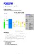
! 4 Module Hardware Overview 4.1 Block Diagram The general HW architecture is shown below Figure: . Module Block Diagram 4.2 Features i i i i i i IEEE802.11a/b/g/n/ac (1X1) based on MTK MT7650U solution. Support BT3.0 USB 2.0 Interface, High and Full Speeds supported. Module is powered by the host with a 5.0V +/- 5% supply. External PCB printed antennas. 4 layers through hole PCB design with FR4 material 4.
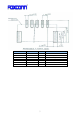
! Pin Number 1 2 3 4 5 S1 S2 Symbol Name GND DP DM UV+ GND GND GND Status I/O I/O P 8! Pin definition Ground USB positive data USB negative data USB +5V power input Ground Ground Ground
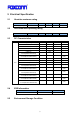
! 5 Electrical Specification 5.1 Absolute maximum rating ! Element DC supply voltage 5.2 Symbol UV+ Min Typ 5.0 Max 6.5 Unit (V) Typ 5.0 Max 5.5 Unit (V) Recommended operating rating ! Element DC supply voltage 5.3 Symbol UV+ Min 4.5 DC Characteristics Symbol UV+ Parameter Supply voltage Min 4.5 2.4GHz Tx Current(1M/15dBm) 2.4GHz Tx Current(11M/15dBm) 2.4GHz Tx Current(6M/15dBm) 2.4GHz Tx Current(54M/15dBm) 2.4GHz Tx Current(MCS0/15Bm/HT20) 2.
! ! Environment condition !!!!!!!!!!!!!!!!!!!!!!!!!!!!!!!!!!!! Operating Temperature: -10 deg.C ~70 deg.C Temperature !!!!!!!!!!!!!!!!!!!!!!!!!!!! Storage Temperature: -40 deg.C ~85 deg.
! 6 RF Specification 6.1 IEEE802.11b!!!!!!!!!!!!!!!!!!!!!!!!!!!!!!!!!!!!!!!!!!!!!!!!!!! Items Specification Mode Channel Data rate TX Characteristics 1. Power Levels (Calibrated) 1) Target Power@1Mbps 2) Target Power@2Mbps 3) Target Power@5.5Mbps 4) Target Power@11Mbps 2. Spectrum Mask @15dBm 1) fc-33MHz І f І fc-22MHz 2) fc-22MHz І f І fc-11MHz 3) fc+11MHz І f І fc+22MHz 4) fc+22MHz І f І fc+33MHz 3. Frequency Error 4 Modulation Accuracy(EVM)@15dBm 1) 1Mbps 2) 2Mbps 3) 5.
! 6.2 IEEE802.11g Items Contents Specification Mode Channel Data rate TX Characteristics 1. Power Levels (Calibrated) 1) Target Power@6Mbps 2) Target Power@9Mbps 3) Target Power@12Mbps 4) Target Power@18Mbps 5) Target Power@24Mbps 6) Target Power@36Mbps 7) Target Power@48Mbps 8) Target Power@54Mbps 2.
! 6.3 802.11n HT20 Items Contents Specification Mode Channel Data rate (MCS index) TX Characteristics 1. Power Levels (Calibrated) 1) Target Power@MCS0 2) Target Power@ MCS1 3) Target Power@ MCS2 4) Target Power@ MCS3 5) Target Power@ MCS4 6) Target Power@ MCS5 7) Target Power@ MCS6 8) Target Power@ MCS7 2. Spectrum Mask @15dBm 1) at fc +/- 11MHz 2) at fc +/- 20MHz 3) at fc > +/-30MHz 3. Modulation Accuracy(EVM)@15dBm 1) MCS0 2) MCS1 3) MCS2 4) MCS3 5) MCS4 6) MCS5 7) MCS6 8) MCS7 4.
! Items Contents Specification Mode Channel Data rate (MCS index) TX Characteristics 1. Power Levels (Calibrated) 1) Target Power@MCS0 2) Target Power@ MCS1 3) Target Power@ MCS2 4) Target Power@ MCS3 5) Target Power@ MCS4 6) Target Power@ MCS5 7) Target Power@ MCS6 8) Target Power@ MCS7 2. Spectrum Mask @15dBm 1) at fc +/- 11MHz 2) at fc +/- 20MHz 3) at fc > +/-30MHz 3. Modulation Accuracy(EVM)@15dBm 1) MCS0 2) MCS1 3) MCS2 4) MCS3 5) MCS4 6) MCS5 7) MCS6 8) MCS7 4. Frequency Error RX Characteristics 5.
! 6.4 802.11a Items Contents Specification Mode Channel Data rate TX Characteristics 1. Power Levels (Calibrated) 1) Target Power@6Mbps 2) Target Power@9Mbps 3) Target Power@12Mbps 4) Target Power@18Mbps 5) Target Power@24Mbps 6) Target Power@36Mbps 7) Target Power@48Mbps 8) Target Power@54Mbps 2.
! 6.5 802.11an HT20 Items Contents Specification Mode Channel Data rate (MCS index) TX Characteristics 1. Power Levels (Calibrated) 1) Target Power@MCS0 2) Target Power@ MCS1 3) Target Power@ MCS2 4) Target Power@ MCS3 5) Target Power@ MCS4 6) Target Power@ MCS5 7) Target Power@ MCS6 8) Target Power@ MCS7 2. Spectrum Mask @15dBm 1) at fc +/- 11MHz 2) at fc +/- 20MHz 3) at fc > +/-30MHz 3. Modulation Accuracy(EVM)@15dBm 1) MCS0 2) MCS1 3) MCS2 4) MCS3 5) MCS4 6) MCS5 7) MCS6 8) MCS7 4.
! 6.6 802.11an HT40 ! Items Contents Specification Mode Channel Data rate (MCS index) TX Characteristics 1. Power Levels (Calibrated) 1) Target Power@MCS0 2) Target Power@ MCS1 3) Target Power@ MCS2 4) Target Power@ MCS3 5) Target Power@ MCS4 6) Target Power@ MCS5 7) Target Power@ MCS6 8) Target Power@ MCS7 2. Spectrum Mask @15dBm 1) at fc +/- 11MHz 2) at fc +/- 20MHz 3) at fc > +/-30MHz 3. Modulation Accuracy(EVM)@15dBm 1) MCS0 2) MCS1 3) MCS2 4) MCS3 5) MCS4 6) MCS5 7) MCS6 8) MCS7 4.
! 6.7 802.11ac HT80 Items Contents Specification Mode Channel Data rate (MCS index) TX Characteristics 1. Power Levels (Calibrated) 1) Target Power@MCS0 2) Target Power@ MCS1 3) Target Power@ MCS2 4) Target Power@ MCS3 5) Target Power@ MCS4 6) Target Power@ MCS5 7) Target Power@ MCS6 8) Target Power@ MCS7 2. Spectrum Mask @15dBm 1) at fc +/- 11MHz 2) at fc +/- 20MHz 3) at fc > +/-30MHz 3. Modulation Accuracy(EVM)@15dBm 1) MCS0 2) MCS1 3) MCS2 4) MCS3 5) MCS4 6) MCS5 7) MCS6 8) MCS7 4.
! 6.8 Bluetooth 3.0 Items Contents Min. Max. Unit 0 2 dBm -75 0 75 kHz DH1 DH3 -20 -20 0 0 20 20 kHz/50us kHz/50us DH5 Average Drift -20 0 20 kHz/50us DH1 -25 0 25 DH3 -40 0 40 kHz kHz DH5 -40 0 40 F1avg 140 150 175 F2max 115 140 F1/F2 Ratio 0.8 0.96 -75 0 - TX Characteristics - Typ. ! 1. Power Levels BT Output Power (Basic Data Rate) -3 2. Initial Carrier Frequency Tolerance Average Offset 3. Carrier Drift Drift Rate kHz 4.
! 6.9 Antenna Electrical Specification ! Parameter Value Units 2.4 ~ 2.4835 5.15~5.85 GHz Antenna gain (max) -0.4 1.12 dBi (Main Antenna) Antenna gain (max) 0.28 0.
! 7 Mechanical Specifications 7.1 Shielding Cover Dimension Dimension (LxWxH): 25.19mm x 18.56mm x 2.0mm Thickness: 0.
! 7.2 PCB Assembly Dimension Dimension (W x Lx H ): 63.8mmx20mmx1.0mm PCB: 4 layer HF-FR4 design Industry Canada statement: This device complies with RSS-210 of the Industry Canada Rules. Operation is subject to the following two conditions: (1) This device may not cause harmful interference, and (2) this device must accept any interference received, including interference that may cause undesired operation.
! However, the OEM integrator is still responsible for testing their end-product for any additional compliance requirements required with this module installed. Cet appareil est conçu uniquement pour les intégrateurs OEM dans les conditions suivantes: (Pour utilisation de dispositif module) 1) L'antenne doit être installée de telle sorte qu'une distance de 20 cm est respectée entre l'antenne et les utilisateurs, et 2) Le module émetteur peut ne pas être coïmplanté avec un autre émetteur ou antenne.
! 5470-5725 MHz shall comply with the e.i.r.p. limit; and (iii) the maximum antenna gain permitted for devices in the band 5725-5825 MHz shall comply with the e.i.r.p. limits specified for point-to-point and non point-to-point operation as appropriate. (iv) Users should also be advised that high-power radars are allocated as primary users (i.e. priority users) of the bands 5250-5350 MHz and 5650-5850 MHz and that these radars could cause interference and/or damage to LE-LAN devices.
! responsible for compliance could void the user's authority to operate this equipment. This transmitter must not be co-located or operating in conjunction with any other antenna or transmitter. ! Operations in the 5.15-5.25GHz band are restricted to indoor usage only. Radiation Exposure Statement: This equipment complies with FCC radiation exposure limits set forth for an uncontrolled environment. This equipment should be installed and operated with minimum distance 20cm between the radiator & your body.
! Europe – EU Declaration of Conformity This device complies with the essential requirements of the R&TTE Directive 1999/5/EC.
! 37!