
User's Manual


!
6!
3 Signal Description
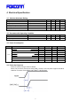
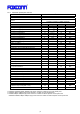
3.1 Signal Diagram
Below figure 2 shows its signal diagram.
Figure 2: Module Signal Diagram
3.2 Pinouts
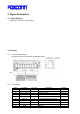
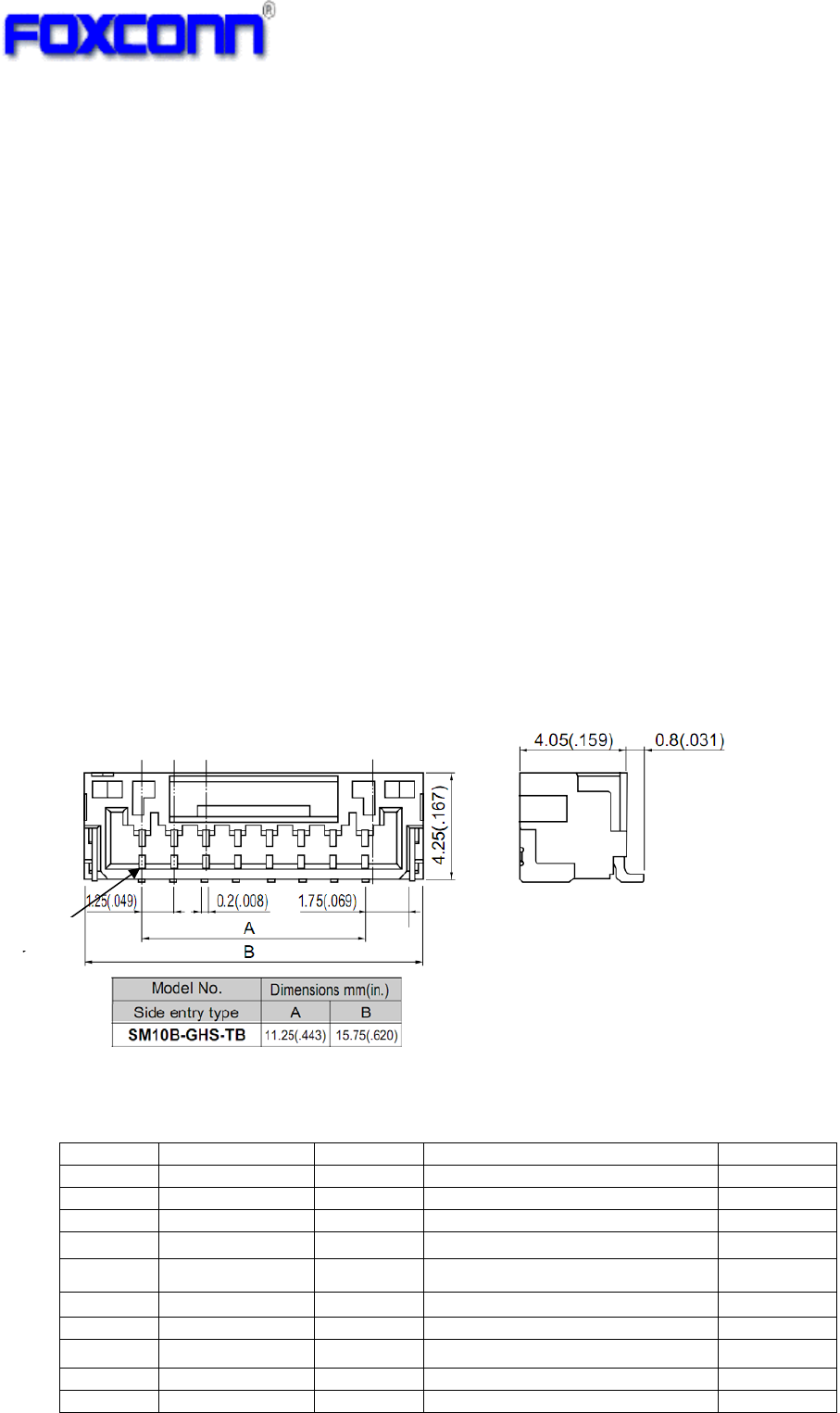
3.2.1 Connector Specification
JST WTB connector, Part Number: SM10B-GHS-TB(LF)
!
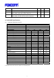
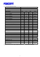
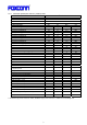
3.2.2 Pin definition
Pin# Pin Name Pin Type Description Remark
1 GND - Ground
2 WoW O Wake-up on wireless LAN Active high
3 CHIP_PWD_L I Reset to module Active low
4 GND -
Ground
5 USB_DM I/O
USB differential signal negative
6 USB_DP I/O
USB differential signal positive
7 VCC_3.3V Power 3.3V power supply +/-5%
8 VCC_3.3V Power
3.3V power supply +/-5%
9 GND -
Ground
10 GND - Ground
Pin1