Installations- und Bedienungsanleitung Installation instruction and operating manual Multi IO Box (DE) S. 2 Multi IO Box (EN) p.
Lieferumfang Anzahl Bezeichnung 1 Homematic IP Multi IO Box 4 Schrauben 4,0 x 40 mm 4 Dübel 6 mm 1 Bedienungsanleitung Dokumentation © 2016 eQ-3 AG, Germany Alle Rechte vorbehalten. Ohne schriftliche Zustimmung des Herausgebers darf diese Anleitung auch nicht auszugsweise in irgendeiner Form reproduziert werden oder unter Verwendung elektronischer, mechanischer oder chemischer Verfahren vervielfältigt oder verarbeitet werden.
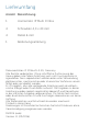
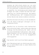
1 A B C E G D F I H J
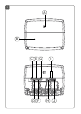
- 93,5 mm - 2 - 16 8m 3 m-
4 5
Inhaltsverzeichnis 1 2 3 4 5 6 Hinweise zur Anleitung....................................................8 Gefahrenhinweise.............................................................8 Funktion und Geräteübersicht..................................... 12 Allgemeine Systeminformationen............................... 13 Montage............................................................................ 14 Inbetriebnahme............................................................... 15 6.1 6.2 6.3 6.
8 9 10 11 Wiederherstellung der Werkseinstellungen...............33 Wartung und Reinigung.................................................33 Allgemeine Hinweise zum Funkbetrieb......................34 Technische Daten...........................................................
Hinweise zur Anleitung 1 Hinweise zur Anleitung Lesen Sie diese Anleitung sorgfältig, bevor Sie Ihr Homematic IP Gerät in Betrieb nehmen. Bewahren Sie die Anleitung zum späteren Nachschlagen auf! Wenn Sie das Gerät anderen Personen zur Nutzung überlassen, übergeben Sie auch diese Anleitung. Benutzte Symbole: Achtung! Hier wird auf eine Gefahr hingewiesen. Hinweis. Dieser Abschnitt enthält zusätzliche wichtige Informationen! 2 Gefahrenhinweise Öffnen Sie das Gerät nicht.
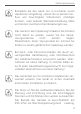
Gefahrenhinweise Betreiben Sie das Gerät nur in trockener sowie staubfreier Umgebung, setzen Sie es keinem Einfluss von Feuchtigkeit, Vibrationen, ständiger Sonnen- oder anderer Wärmeeinstrahlung, Kälte und keinen mechanischen Belastungen aus. Das Gerät ist kein Spielzeug! Erlauben Sie Kindern nicht damit zu spielen. Lassen Sie das Verpackungsmaterial nicht achtlos liegen. Plastikfolien/-tüten, Styroporteile etc. können für Kinder zu einem gefährlichen Spielzeug werden.
Gefahrenhinweise Arbeiten am 230-V-Netz dürfen nur von einer Elektrofachkraft (nach VDE 0100) erfolgen. Dabei sind die geltenden Unfallverhütungsvorschriften zu beachten. Zur Vermeidung eines elektrischen Schlages am Gerät, schalten Sie bitte die Netzspannung frei (Sicherungsautomat abschalten). Bei Nichtbeachtung der Installationshinweise können Brand oder andere Gefahren entstehen. Beachten Sie beim Anschluss an die Geräteklemmen die hierfür zulässigen Leitungen und Leitungsquerschnitte.
Gefahrenhinweise Vor dem Anschließen des Aktors muss die Sicherung im Sicherungskasten herausgenommen werden. Beachten Sie die Installationsvorschriften für Installationen in Verteilersystemen (DIN VDE 0100410). Die Steuerspannung des 0 bis 10-V-Ausgangs ist potentialgetrennt vom Netzpotential. Sie ist allerdings keine Schutzkleinspannung (SELV). Dies ist bei Leitungsführung, Installation und Anschluss zu beachten. Das Gerät ist nur für den Einsatz in wohnungsähnlichen Umgebungen geeignet.
Funktion und Geräteübersicht 3 Funktion und Geräteübersicht Die Homematic IP Multi IO Box ist die zentrale Steuereinheit für das Schalten von Umwälzpumpen, Heizkesseln und Zirkulationspumpen. Das Gerät ermöglicht eine komfortable und bedarfsgerechte Regelung der Raumbzw. Wassertemperatur per Smartphone App nach Ihren individuellen Bedürfnissen. Über die Multi IO Box kann die Heizungsanlage von Heizbetrieb auf Kühlbetrieb umgeschaltet werden, um so über die Fußbodenheizung die Raumtemperatur zu senken.
Allgemeine Systeminformationen (F) (G) (H) (I) (J) 4 Anschlussklemme 4 (z. B. für den Anschluss eines Heizkessels) Anschlussklemme 5 (Wechselklemme, z. B. für den Anschluss einer Umwälzpumpe) LED-Leuchten zur Anschlussanzeige Anschlussklemmen für IN1/IN2 (Heiz-, Kühl- oder Ecobetrieb, Temperatur- oder Feuchtebegrenzer) Anschlussklemmen für AOUT (0 - 10 V Ausgang, z. B.
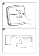
Montage 5 Montage Sie können die Multi IO Box mit den mitgelieferten Schrauben und Dübeln frei an der Wand montieren In Verbindung mit dem optional erhältlichen Hutschienenadapter (HmIP-DRA) können Sie die Multi IO Box auch auf einer Hutschiene montieren. Weitere Informationen dazu entnehmen Sie bitte der Bedienungsanleitung des Hutschienenadapters.
Inbetriebnahme 6 Inbetriebnahme 6.1 Installationshinweise Bitte lesen Sie diesen Abschnitt erst vollständig, bevor Sie mit der Installation beginnen. Hinweis! Installation nur durch Personen mit einschlägigen elektrotechnischen Kenntnissen und Erfahrungen!* Durch eine unsachgemäße Installation gefährden Sie • Ihr eigenes Leben; • das Leben der Nutzer der elektrischen Anlage. Mit einer unsachgemäßen Installation riskieren Sie schwere Sachschäden, z. B. durch Brand.
Inbetriebnahme • • • der Abschaltbedingungen; IP-Schutzarten; Einbau des Elektroinstallationsmaterials; Art des Versorgungsnetzes (TN-System, IT-System, TT-System) und die daraus folgenden Anschlussbedingungen (klassische Nullung, Schutzerdung, erforderliche Zusatzmaßnahmen etc.). Für den Einbau der Multi IO Box in einen Stromkreisverteiler, muss das Gerät entsprechend VDE 0603, DIN 43871 (Niederspannungsunterverteilung (NSUV)), DIN 18015-x eingebaut werden.
Inbetriebnahme erreichbar und als Trennvorrichtung für das Gerät gekennzeichnet sein. Beachten Sie bei der Installation die Gefahrenhinweise gemäß „2 Gefahrenhinweise“ auf Seite 2.
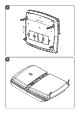
Inbetriebnahme 6.2 Installation Für eine komfortable Installation können Sie die Kabel durch die Kabeldurchführungen ziehen, nachdem Sie die Ausbrechöffnungen entfernt haben. Für die Installation der Multi IO Box gehen Sie wie folgt vor: • Öffnen Sie die Abdeckung (B), indem Sie die beiden unteren Schrauben mit einem geeigneten Schraubendreher lösen und die Abdeckung abnehmen (s. Abbildung 3). • Schließen Sie den Schutzleiter an die Anschlussklemme für PE (C) an.
Inbetriebnahme die Rastnasen der Abdeckung in die vorgesehenen Öffnungen schieben und die Schrauben festdrehen. 6.3 Anschlussmöglichkeiten 6.3.1 Anschluss Kessel PE 1.1 PE 1.2 L 2.1 L 2.2 N 3.1 N 3.2 1▼ 4.1 L▲ 4.2 2▼ 5.1 L▲ 5.2 1▼ 5.
Inbetriebnahme 6.3.2 Anschluss Luftentfeuchter Diese Anschlussmöglichkeit können Sie nur in Verbindung mit einem Homematic IP Access Point oder einer Homematic Zentrale CCU2 realisieren. PE 1.1 N L 20 PE 1.2 L 2.1 L 2.2 N 3.1 N 3.2 1▼ 4.1 L▲ 4.2 2▼ 5.1 L▲ 5.2 1▼ 5.
Inbetriebnahme 6.3.3 Anschluss Change-Over-Pilot Diese Anschlussmöglichkeit können Sie nur in Verbindung mit einem Homematic IP Access Point oder einer Homematic Zentrale CCU2 realisieren. PE 1.1 PE 1.2 L 2.1 L 2.2 N 3.1 N 3.2 1▼ 4.1 L▲ 4.2 2▼ 5.1 L▲ 5.2 1▼ 5.
Inbetriebnahme 6.3.4 Anschluss Pumpe PE 1.1 N L 22 PE 1.2 L 2.1 L 2.2 N 3.1 N 3.2 1▼ 4.1 L▲ 4.2 2▼ 5.1 L▲ 5.2 1▼ 5.
Inbetriebnahme Anschluss Feuchtefühler 4.2 IN1 GND 6.2 ▼ 6.3 GND 6.4 ▼ 6.5 AOUT ▼ 6.1 IN2 IN2 C/O IN1 6.3.5 GND 6.
Inbetriebnahme 6.3.6 Anschluss externes Change-Over-Signal 4.2 IN1 GND 6.2 ▼ 6.3 GND 6.4 ▼ 6.5 AOUT ▼ 6.1 IN2 C/O IN1 IN2 GND 6.
Inbetriebnahme 6.3.7 Anschluss externe Schaltuhr Diese Anschlussmöglichkeit können Sie nur in Verbindung mit einem Homematic IP Access Point oder einer Homematic Zentrale CCU2 realisieren. 4.2 IN1 L 2.2 N 3.1 N 3.2 1▼ 4.1 L▲ 4.2 2▼ 5.1 L▲ 5.2 1▼ 5.3 C/O ▼ 6.1 GND 6.2 ▼ 6.3 IN2 L 2.1 GND 6.4 ▼ 6.5 AOUT PE 1.2 IN1 IN2 PE 1.1 GND 6.6 L N 6.3.
Inbetriebnahme 6.4 Anlernen Bitte lesen Sie diesen Abschnitt erst vollständig, bevor Sie mit dem Anlernen beginnen. Damit die Multi IO Box in Ihr System integriert werden und mit anderen Geräten kommunizieren kann, muss sie zunächst angelernt werden. Sie können die Multi IO Box entweder direkt an den Homematic IP Fußbodenheizungsaktor oder an den Homematic IP Access Point anlernen. Beim Anlernen an den Access Point erfolgt die Konfiguration über die Homematic IP App. 6.4.
Inbetriebnahme Wenn Sie die Multi IO Box an einen Homematic IP Fußbodenheizungsaktor anlernen möchten, müssen die beiden zu verknüpfenden Geräte in den Anlernmodus gebracht werden. Dafür gehen Sie wie folgt vor: • Drücken Sie die Systemtaste (A) der Multi IO Box für mind. 4 s, um den Anlernmodus zu aktivieren (s. Abbildung 4). Die Geräte-LED blinkt orange. • Aktivieren Sie nun den Anlernmodus am Fußbodenheizungsaktor.
Inbetriebnahme 6.4.2 Anlernen an den Homematic IP Access Point Richten Sie zunächst Ihren Homematic IP Access Point über die Homematic IP App ein, um weitere Homematic IP Geräte im System nutzen zu können. Ausführliche Informationen dazu finden Sie in der Bedienungsanleitung des Access Points. Sie können das Gerät sowohl an den Access Point als auch an die Homematic Zentrale CCU2 anlernen.
Fehlerbehebung • • • • • • • Das Gerät erscheint automatisch in der Homematic IP App. Zur Bestätigung geben Sie in der App die letzten vier Ziffern der Gerätenummer (SGTIN) ein oder scannen Sie den QR-Code des Geräts. Die Gerätenummer finden Sie auf dem Aufkleber im Lieferumfang oder direkt am Gerät. Warten Sie, bis der Anlernvorgang abgeschlossen ist. Zur Bestätigung eines erfolgreichen Anlernvorgangs leuchtet die LED grün. Das Gerät ist nun einsatzbereit. Leuchtet die LED rot, versuchen Sie es erneut.
Fehlerbehebung • • • 7.2 Empfänger nicht erreichbar, Empfänger kann Befehl nicht ausführen (Lastausfall, mechanische Blockade etc.) oder Empfänger defekt. Duty Cycle Der Duty Cycle beschreibt eine gesetzlich geregelte Begrenzung der Sendezeit von Geräten im 868-MHz-Bereich. Das Ziel dieser Regelung ist es, die Funktion aller im 868 MHz Bereich arbeitenden Geräte zu gewährleisten.
Fehlerbehebung 7.3 Fehlercodes und Blinkfolgen Blinkcode Bedeutung Kurzes oranges Blinken Funkübertragung/ Warten Sie, bis die Sendeversuch/ Übertragung beenDatenübertragung det ist. 1x langes grünes Leuchten Vorgang bestätigt Sie können mit der Bedienung fortfahren. 1x langes rotes Leuchten Vorgang fehlgeschlagen Versuchen Sie es erneut (s. „7.1 Befehl nicht bestätigt“ auf Seite 29).
Fehlerbehebung Schnelles oranges Blinken Anlernmodus beider Verknüpfungspartner aktiv (direktes Anlernen) Warten Sie auf die Rückmeldung durch die Geräte-LED (s. „7.3 Fehlercodes und Blinkfolgen“ auf Seite 31). 1x langes rotes Leuchten Vorgang fehlgeschlagen oder Duty-Cycle-Limit erreicht Versuchen Sie es erneut („7.1 Befehl nicht bestätigt“ auf Seite 29 oder „7.2 Duty Cycle“ auf Seite 30).
Wiederherstellung der Werkseinstellungen 8 Wiederherstellung der Werkseinstellungen Die Werkseinstellungen des Gerätes können wiederhergestellt werden. Dabei gehen alle Einstellungen verloren. Um die Werkseinstellungen der Multi IO Box wiederherzustellen, gehen Sie wie folgt vor: • Drücken Sie für 4 s auf die Systemtaste (A), bis die LED schnell orange zu blinken beginnt (s. Abbildung 4). • Lassen Sie die Systemtaste wieder los. • Drücken Sie die Systemtaste erneut für 4 s, bis die LED grün aufleuchtet.
Allgemeine Hinweise zum Funkbetrieb trockenen und fusselfreien Tuch. Verwenden Sie keine lösemittelhaltigen Reinigungsmittel, das Kunststoffgehäuse und die Beschriftung können dadurch angegriffen werden. 10 Allgemeine Hinweise zum Funkbetrieb Die Funk-Übertragung wird auf einem nicht exklusiven Übertragungsweg realisiert, weshalb Störungen nicht ausgeschlossen werden können. Weitere Störeinflüsse können hervorgerufen werden durch Schaltvorgänge, Elektromotoren oder defekte Elektrogeräte.
Technische Daten 11 Technische Daten Geräte-Kurzbezeichnung: Versorgungsspannung: Stromaufnahme: Leistungsaufnahme Ruhebetrieb: Max. Schaltleistung: Ausgang 1: HmIP-MIOB 230 V/50 Hz 16 A max. 250 mW 3680 W, cosφ≥0,95 (potentialfrei) Ausgang 2: 1840 W, cosφ≥0,95 (potentialfrei) Leitungsart u. -querschnitt: starre und flexible Leitung, 0,75 - 2,5 mm² Lastart: ohmsche Last Wirkungsweise: Typ 1.
Technische Daten Schutzart: Schutzklasse: Umgebungstemperatur: Abmessung (B x H x T ): Gewicht: Funkfrequenz: Empfängerkategorie: Typ. Funk-Freifeldreichweite: Duty Cycle: IP20 I 0 - 50 °C 199 x 156 x 34 mm 365 g 868,3 MHz/869,525 MHz SRD category 2 380 m < 1% pro h/< 10% pro h Technische Änderungen vorbehalten.
Package contents Quantity Description 1 Homematic IP Multi IO Box 4 Screws 4.0 x 40 mm 4 Plugs 6 mm 1 Operating manual 2 Plugs 5 mm 1 Operating manual Documentation © 2016 eQ-3 AG, Germany All rights reserved. Translation of the original version in German. This manual may not be reproduced in any format, either in whole or in part, nor may it be duplicated or edited by electronic, mechanical or chemical means, without the written consent of the publisher.
Table of contents 1 2 3 4 5 6 Information about this manual................................... 40 Hazard information........................................................ 40 Function and device overview.....................................43 General system information.........................................45 Mounting...........................................................................45 Start-up............................................................................ 46 6.1 6.2 6.3 6.
8 9 10 11 Restore factory settings.................................................63 Maintenance and cleaning........................................... 64 General information about radio operation............. 64 Technical specifications.................................................
Information about this manual 1 Information about this manual Please read this manual carefully before beginning operation with your Homematic IP component. Keep the manual so you can refer to it at a later date if you need to. If you hand over the device to other persons for use, please hand over this manual as well. Symbols used: Attention! This indicates a hazard. Please note: This section contains important additional information. 2 Hazard information Do not open the device.
Hazard information The device may only be operated in dry and dustfree environment and must be protected from the effects of moisture, vibrations, solar or other methods of heat radiation, cold and mechanical loads. The device is not a toy; do not allow children to play with it. Do not leave packaging material lying around. Plastic films/bags, pieces of polystyrene, etc. can be dangerous in the hands of a child.
Hazard information to carry out work on the 230 V mains. Applicable accident prevention regulations must be complied with whilst such work is being carried out. To avoid electric shocks from the device, please disconnect the mains voltage (trip the miniature circuit-breaker). Noncompliance with the installation instructions can cause fire or introduce other hazards. When connecting to the device terminals, take the permissible cables and cable cross sections into account.
Function and device overview Observe the installation instructions for installation in distribution systems (DIN VDE 0100410). The control voltage of the 0 to 10 V output is electrically isolated from the mains potential but is not at safety extra-low voltage (SELV). This must be observed during cable routing, installation and connection. The device may only be operated within residential buildings.
Function and device overview room temperature using the floor heating. Thanks to the input for a humidity and temperature limiter, mould formation caused by condensation water on the cables or overheating of the heating system can be reliably avoided. You can flexibly mount the device using the supplied screws or the Homematic IP DIN-Rail Adapter HmIP-DRA (available as an option).
General system information 4 General system information This device is part of the Homematic IP smart home system and works with the HmIP radio protocol. In connection with the Homematic IP Access Point, the Homematic IP Multi IO Box can be configured comfortably and individually with a smartphone using the Homematic IP app. The available functions provided by the Homematic IP system in combination with other components are described in the Homematic IP User Guide.
Start-up Make sure that no electricity or similar lines run in the wall at this location! • • • Use a pen to mark the positions of the four bore holes on the wall (see fig. 2). Use an appropriate drill to make the 6 mm holes as illustrated. Use the screws and plugs supplied to fasten the Multi IO Box (see fig. 2). 6 Start-up 6.1 Installation instructions Please read this entire section before starting to install the device.
Start-up Contact an electrical installer! *Specialist knowledge required for installation: The following specialist knowledge is particularly important during installation: • The “5 safety rules” to be used: Disconnect from mains; Safeguard from switching on again; Check that system is deenergised; Earth and short circuit; Cover or cordon off neighbouring live parts; • Select suitable tool, measuring equipment and, if necessary, personal safety equipment; • Evaluation of measuring results; • Selection of e
Start-up The circuit to the which the device and the load will be connected has to be secured by a cable protection switch in accordance with EN60898-1 (tripping characteristic B or C, max. 16 A rated current, min. 6 kA interrupting rating, energy limiting class 3). Installation regulations according to VDE 0100 and HD382 or 60364 have to be considered. Users must be able to easily access the cable protection switch. This must be marked as disconnecting device for the actuator.
Start-up 6.2 Installation For comfortable installation you can pull the cable through the cable inlets after having removed the breakout openings. To install the Multi IO Box, please proceed as follows: • Open the cover (B). Therefore, unscrew both lower screws with an appropriate screwdriver and remove the cover afterwards (see fig. 3). • Connect the protective conductor to connecting terminal PE (C). • Connect the phase conductor to connecting terminal L (D) .
Start-up 6.3 Connections 6.3.1 Boiler connection PE 1.1 N L 50 PE 1.2 L 2.1 L 2.2 N 3.1 N 3.2 1▼ 4.1 L▲ 4.2 2▼ 5.1 L▲ 5.2 1▼ 5.
Start-up 6.3.2 Air dehumidifier connection This type of connection can be realised only in connection with a Homematic IP Access Point or Homematic Central Control Unit CCU2. PE 1.1 PE 1.2 L 2.1 L 2.2 N 3.1 N 3.2 1▼ 4.1 L▲ 4.2 2▼ 5.1 L▲ 5.2 1▼ 5.
Start-up 6.3.3 Change over pilot supply This type of connection can be realised only in connection with a Homematic IP Access Point or Homematic Central Control Unit CCU2. PE 1.1 PE 1.2 L 2.1 L 2.2 N 3.1 N 3.2 L N L N heating cooling 52 6.3.4 Pump connection 1▼ 4.1 L▲ 4.2 2▼ 5.1 L▲ 5.2 1▼ 5.
Start-up PE 1.1 PE 1.2 L 2.1 L 2.2 N 3.1 N 3.2 1▼ 4.1 L▲ 4.2 2▼ 5.1 L▲ 5.2 1▼ 5.
Start-up 6.3.5 Humidity sensor connection 4.2 IN1 ▼ 6.3 GND 6.4 ▼ 6.5 AOUT GND 6.2 IN2 ▼ 6.1 IN1 IN2 C/O GND 6.
Start-up External changeover signal connection 4.2 IN1 ▼ 6.1 GND 6.2 ▼ 6.3 GND 6.4 ▼ 6.5 AOUT C/O IN2 IN2 IN1 6.3.6 GND 6.
Start-up 6.3.7 External timer connection This type of connection can be realised only in connection with a Homematic IP Access Point or Homematic Central Control Unit CCU2. 4.2 IN1 L 2.2 N 3.1 N 3.2 1▼ 4.1 L▲ 4.2 2▼ 5.1 L▲ 5.2 1▼ 5.3 C/O ▼ 6.1 GND 6.2 ▼ 6.3 IN2 L 2.1 GND 6.4 ▼ 6.5 AOUT PE 1.2 IN1 IN2 PE 1.1 GND 6.6 L N 6.3.
Start-up 6.4 Teaching-in Please read this entire section before starting the teach-in procedure. To integrate the Multi IO Box into your system and enable it to communicate with other devices, you must connect it first. You can either pair the Multi IO Box directly with the Homematic IP Floor Heating Actuator or teach it in to the Homematic IP Access Point. If you teach-in the device to the Access Point, configuration is done via the Homematic IP app. 6.4.
Start-up If you want to pair the Muli IO Box with a Homematic IP Floor Heating Actuator, the pairing mode of both devices has to be activated first. To do this, proceed as follows: • Press and hold down the system button (A) of the Multi IO Box for at least 4 seconds to activate the pairing mode (see figure 4). The device LED flashes orange. • Activate the pairing mode of your floor heating actuator. Briefly press the select button until the LEDs of all channels light up green.
Start-up 6.4.2 Teaching-in to the Homematic IP Access Point First set up your Homematic IP Access Point via the Homematic IP app to enable operation of other Homematic IP devices within your system. For further information, please refer to the operating manual of the Access Point. You can connect the device either to the Access Point or to the Homematic Central Control Unit CCU2. For detailed information, please refer to the Homematic IP User Guide, available for download in the download area of www.eQ-3.
Troubleshooting • • • • • • To confirm, please enter the last four digits of the device number (SGTIN) in your app or scan the QR code of your device. Therefore, please see the sticker supplied or attached to the device. Please wait until teach-in is completed. If teaching-in was successful, the LED lights up green. The device is now ready for use. If the LED lights up red, please try again. Select the desired solution for your device. In the app, give the device a name and allocate it to a room.
Troubleshooting 7.2 Duty cycle The duty cycle is a legally regulated limit of the transmission time of devices in the 868 MHz range. The aim of this regulation is to safeguard the operation of all devices working in the 868 MHz range. In the 868 MHz frequency range we use, the maximum transmission time of any device is 1% of an hour (i.e. 36 seconds in an hour). Devices must cease transmission when they reach the 1% limit until this time restriction comes to an end.
Troubleshooting 7.3 Error codes and flashing sequences Flashing code Meaning Solution Short orange flashing Radio transmission/attempting to transmit/data transmission Wait until the transmission is completed. 1x long green lighting Transmission confirmed You can continue operation. 1x long red lighting Transmission failed Please try again (s. „7.1 Command not confirmed“ on page 60).
Restore factory settings 1x long red lighting Transmission failed or duty cycle limit is reached Please try again (see sec. „7.1 Command not confirmed“ on page 60 or „7.2 Duty cycle“ on page 61). 6x long red flashing Device defective Please see your app for error message or contact your retailer. 1x orange and Test display 1 x green lighting 8 Once the test display has stopped, you can continue. Restore factory settings The factory settings of the device can be restored.
Maintenance and cleaning • 4 seconds, until the status LED lights up green. Release the system button to finish the procedure. The device will perform a restart. After the restart, you can again integrate your device into your Homematic IP system. 9 Maintenance and cleaning The product does not require any maintenance. Enlist the help of an expert to carry out any maintenance or repairs. Clean the device using a soft, lint-free cloth that is clean and dry.
Technical specifications The range of transmission within buildings can differ greatly from that available in the open air. Besides the transmitting power and the reception characteristics of the receiver, environmental factors such as humidity in the vicinity have an important role to play, as do on-site structural/ screening conditions. eQ-3 AG hereby declares that this device complies with the essential requirements and other relevant regulations of Directive 1999/5/EC.
Technical specifications Switching cycle: Relay: 10000 Changeover contact, 1-pole, µ contact NO contact, 1-pole, µ contact Withstand voltage: 4000 V Temperature glow wire test: 850 °C Temperature ball pressure test: 125 °C Construction: Independently mounted electronic regulation and control device Degree of pollution: 2 Degree of protection: IP20 Protection class: I Ambient temperature: 0 - 50°C Dimensions (W x H x D): 199 x 156 x 34 mm Weight: 365 g Radio frequency: 868.3 MHz/869.
Technical specifications Instructions for disposal Do not dispose of the device with regular domestic waste! Electronic equipment must be disposed of at local collection points for waste electronic equipment in compliance with the Waste Electrical and Electronic Equipment Directive. Information about conformity The CE sign is a free trading sign addressed exclusively to the authorities and does not include any warranty of any properties. For technical support, please contact your retailer.
Kostenloser Download der Homematic IP App! Free download of the Homematic IP app! Bevollmächtigter des Herstellers: Manufacturer’s authorised representative: eQ-3 AG Maiburger Straße 29 26789 Leer / GERMANY www.eQ-3.