
Instructions

44
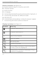
Function and device overview
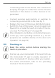
Device overview (see figure 1):
A System button (teach-in button and LED)
B Channel button
C Select button
D LC display
E Connecting terminal for push-button/switch channel 1-4
F Connecting
terminals for dierent loads
G DIN rail lock
H
Connecting terminal phase conductor (power supply)
I Connecting terminal neutral conductor
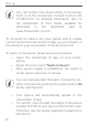
Display overview (see figure 1):
Symbol Meaning
RX
TX
V
1 1
Channel switched on
RX
TX
V
1 1
Channel switched o
RX
TX
V
1 1
1
1
Input not activated
RX
TX
V
1 1
1
1
Input activated
RX
TX
V
1 1
Receiving data
RX
TX
V
1 1
Transmitting data
RX
TX
V
1 1
Percentage (indicated, if switching status
or duty cycle are displayed)
RX
TX
V
1 1
Temperature indication (indicated, if tem-
perature is displayed)