Installations- und Bedienungsanleitung Installation and operating manual Jalousieaktor für Hutschienenmontage – 4-fach S. 2 Blind Actuator for DIN rail mount – 4 channels P.
Lieferumfang Anzahl Bezeichnung 1 Homematic IP Jalousieaktor für Hutschienenmontage – 4-fach 1 Bedienungsanleitung Dokumentation © 2019 eQ-3 AG, Deutschland Alle Rechte vorbehalten. Ohne schriftliche Zustimmung des Herausgebers darf diese Anleitung auch nicht auszugsweise in irgendeiner Form reproduziert werden oder unter Verwendung elektronischer, mechanischer oder chemischer Verfahren vervielfältigt oder verarbeitet werden.
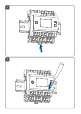
1 B C D A E F G L H K J G I F E
2 OFF 3 1 2
4 5
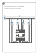
Anschluss des Motors (Ausgänge) Motor connection (outputs)
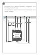
Anschluss von Tastern/Schaltern (Eingänge) und Versorgungsspannung Connection of push-buttons/switches (inputs) and supply voltage
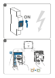
ON 9 HAP Homematic IP
10 11
12 13 4s
14 4s
Inhaltsverzeichnis 1 2 3 4 5 Hinweise zur Anleitung.................................................. 13 Gefahrenhinweise........................................................... 13 Funktion und Geräteübersicht.....................................18 Allgemeine Systeminformationen.............................. 20 Inbetriebnahme.............................................................. 20 5.1 5.2 5.3 6 7 Bedienung.........................................................................
Hinweise zur Anleitung 1 Hinweise zur Anleitung Lesen Sie diese Anleitung sorgfältig, bevor Sie Ihr Homematic IP Gerät in Betrieb nehmen. Bewahren Sie die Anleitung zum späteren Nachschlagen auf! Wenn Sie das Gerät anderen Personen zur Nutzung überlassen, übergeben Sie auch diese Anleitung. Benutzte Symbole: Achtung! Hier wird auf eine Gefahr hingewiesen. Hinweis. Dieser Abschnitt enthält zusätzliche wichtige Informationen. 2 Gefahrenhinweise Öffnen Sie das Gerät nicht.
Gefahrenhinweise Verwenden Sie das Gerät nicht, wenn es von außen erkennbare Schäden, z. B. am Gehäuse, an Bedienelementen oder an den Anschlussbuchsen ausweist. Lassen Sie das Gerät im Zweifelsfall von einer Fachkraft prüfen. Betreiben Sie das Gerät nur in trockener sowie staubfreier Umgebung, setzen Sie es keinem Einfluss von Feuchtigkeit, Vibrationen, ständiger Sonnen- oder anderer Wärmeeinstrahlung, Kälte und keinen mechanischen Belastungen aus.
Gefahrenhinweise Der Aktor ist Teil der Gebäudeinstallation. Bei der Planung und Errichtung sind die einschlägigen Normen und Richtlinien des Landes zu beachten. Der Betrieb des Geräts ist ausschließlich am 230 V/50 Hz-Wechselspannungsnetz zulässig. Arbeiten am 230-V-Netz dürfen nur von einer Elektrofachkraft (nach VDE 0100) erfolgen. Dabei sind die geltenden Unfallverhütungsvorschriften zu beachten.
Gefahrenhinweise Beachten Sie vor Anschluss eines Verbrauchers die technischen Daten, insbesondere die maximal zulässige Schaltleistung der Lastkreise und Art des anzuschließenden Verbrauchers. Belasten Sie den Aktor nur bis zur angegebenen Leistungsgrenze. Die Laststromkreise müssen mit einem Leitungsschutzschalter gemäß EN60898-1 (Auslösecharakteristik B oder C, max. 10 A Nennstrom, min. 6 kA Abschaltvermögen, Energiebegrenzungsklasse 3) abgesichert sein.
Gefahrenhinweise Verwenden Sie nur Jalousien bzw. Rollläden mit Endlagenschalter (mechanisch oder elektronisch). Prüfen Sie die Endlagenschalter der angeschlossenen Motoren vor der Inbetriebnahme des Aktors auf korrekte Justierung. Schließen Sie keine Drehstrommotoren an. Bei Einsatz in einer Sicherheitsanwendung ist das Gerät/System in Verbindung mit einer USV (unterbrechungsfreie Stromversorgung) zu betreiben, um einen möglichen Netzausfall zu überbrücken.
Funktion und Geräteübersicht 3 Funktion und Geräteübersicht Der Homematic IP Jalousieaktor – 4-fach lässt sich einfach auf einer Hutschiene in einem Stromkreisverteiler montieren. Einmal installiert, steuert er angeschlossene Jalousien, Rollläden oder Markisen über vier potentialfreie, unabhängige Kanäle. Der Jalousieaktor ermöglicht eine komfortable Steuerung angeschlossener Jalousie-, Rollladen- bzw.
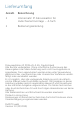
Funktion und Geräteübersicht Displayübersicht (s. Abbildung 1): Symbol Bedeutung Kanal eingeschaltet 1 1 Kanal ausgeschaltet RX 1 1 V 1 TX111RX 11 1 TX V V V Eingang betätigt 1 RX 1 11RX1 1 1 1 TX TX RX RX RX TX TX TX Eingang nicht betätigt RX TX Daten werden empfangen 1 V V Daten werden gesendet Höhe der Jalousie bzw.
Allgemeine Systeminformationen 4 Allgemeine Systeminformationen Dieses Gerät ist Teil des Homematic IP Smart-HomeSystems und kommuniziert über das Homematic IP Funkprotokoll. Alle Geräte des Systems können komfortabel und individuell per Smartphone über die Homematic IP App konfiguriert werden. Alternativ haben Sie die Möglichkeit, Homematic IP Geräte über die Zentrale CCU2/CCU3 oder in Verbindung mit vielen Partnerlösungen zu betreiben.
Inbetriebnahme Durch eine unsachgemäße Installation gefährden Sie • Ihr eigenes Leben; das Leben der Nutzer der elektrischen Anlage. • Mit einer unsachgemäßen Installation riskieren Sie schwere Sachschäden, z. B. durch Brand. Es droht für Sie die persönliche Haftung bei Personen- und Sachschäden.
Inbetriebnahme Beachten Sie die auf dem Gerät angegebene Abisolierlänge der anzuschließenden Leiter. Zugelassene Leitungsquerschnitte zum Anschluss an den Jalousieaktor sind: Starre Leitung [mm2] Flexible Leitung ohne Aderendhülse [mm2] 0,75 – 2,50 0,75 – 2,50 5.2 Montage und Installation Bitte lesen Sie diesen Abschnitt erst vollständig, bevor Sie mit der Installation beginnen.
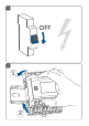
Inbetriebnahme • • • • • (s. Abbildung 4). Verdrahten Sie das Gerät gemäß den Anschlusszeichnungen in Abbildung 6 oder 7. Schließen Sie zur Versorgung des Jalousieaktors den Neutralleiter an die Klemme K und den Außenleiter an die Klemme J an (s. Abbildung 7). Es können beliebige Außenleiter (L1, L2, L3) angeschlossen werden. Schließen Sie den Außenleiter für den gewünschten Kanal an die entsprechende Klemme (G) an (s. Abbildung 6).
Inbetriebnahme Die Netzklemmen dürfen nur zum Anschluss der Netzspannung an das Gerät bzw. zum Anschluss von Verbrauchern an das Gerät verwendet werden. Das Weiterverbinden (Durchschleifen) von Leitern über die Netzklemmen des Geräts zu anderen Geräten ist nicht erlaubt! • • • Schließen Sie die externen Taster/Schalter wie folgt an die Anschlussklemme 1 bis 8 an (s.
Inbetriebnahme 5.3 Anlernen Bitte lesen Sie diesen Abschnitt erst vollständig, bevor Sie mit dem Anlernen beginnen. Richten Sie zunächst Ihren Homematic IP Access Point über die Homematic IP App ein, um weitere Homematic IP Geräte im System nutzen zu können. Ausführliche Informationen dazu finden Sie in der Bedienungsanleitung des Access Points. Sie können das Gerät an den Access Point oder an die Zentrale CCU2/CCU3 anlernen.
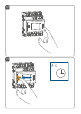
Inbetriebnahme Sie können den Anlernmodus manuell für weitere 3 Minuten starten, indem Sie die Systemtaste (A) kurz drücken (s. Abbildung 9). • • • • • • • 26 Das Gerät erscheint automatisch in der Homematic IP App. Zur Bestätigung geben Sie in der App die letzten vier Ziffern der Gerätenummer (SGTIN) ein oder scannen Sie den QR-Code. Die Gerätenummer finden Sie auf dem Aufkleber im Lieferumfang oder direkt am Gerät. Warten Sie, bis der Anlernvorgang abgeschlossen ist.
Bedienung 6 Bedienung Über die folgenden Tasten stehen Ihnen einfache Bedienfunktionen direkt am Gerät zur Verfügung: • Systemtaste (A) • Channel-Taste (B) • Select-Taste (C) • externe Taster/Schalter (H und L) Systemtaste Durch kurzes Drücken der Systemtaste (s. Abbildung 10) können Sie die LCD-Hintergrundbeleuchtung aktivieren. Channel-Taste Durch kurzes Drücken der Channel-Taste (s. Abbildung 11) können Sie den gewünschten Kanal auswählen. Bei jeder Betätigung wird ein Kanal weiter 1 1 geschaltet.
Bedienung Symbol Bedeutung Runterfahren Hochfahren Stopp Select-Taste Wenn Sie über die Channel-Taste einen Kanal ausgewählt haben (s. Channel-Taste), können Sie durch kurzes Drücken der Select-Taste (s. Abbildung 12) den Zustand des Ausgangskanals (Runterfahren - Stopp - Hochfahren - Stopp usw.) auswählen. Bei jeder Betätigung wird ein Zustand weiter geschaltet. Bei den Eingangskanälen wird durch Drücken der Select-Taste ein kurzer Tastendruck für den ausgewählten Eingang simuliert.
Bedienung Externe Taster/Schalter Mit den externen Tastern/Schaltern kann jeder Kanal direkt rauf- bzw. runterfahren werden. Taster: • Kurzer Tastendruck Taste für Kanal 1, 3, 5, 7: Der Motor für die Rollläden oder die Markise fährt bis zur Endposition runter. • Kurzer Tastendruck Taste für Kanal 2, 4, 6, 8: Der Motor für die Rollläden oder die Markise fährt bis zur Endposition rauf. • Kurzer Tastendruck entgegengesetzte Richtung: Der Motor stoppt.
Fehlerbehebung 7 Fehlerbehebung 7.1 Fehlercodes und Blinkfolgen Blinkcode/ LCD-Anzeige Bedeutung Lösung Kurzes oranges Blinken (alle 10 s) Anlernmodus aktiv Geben Sie die letzten vier Ziffern der GeräteSeriennummer zur Bestätigung ein (s. „5.3 Anlernen“ auf Seite 25). 6x langes rotes Blinken Gerät defekt Achten Sie auf die Anzeige in Ihrer App oder wenden Sie sich an Ihren Fachhändler. 1x oranges und 1x grünes Leuchten Testanzeige Nachdem die Testanzeige erloschen ist, können Sie fortfahren.
Fehlerbehebung 7.2 Befehl nicht bestätigt Bestätigt mindestens ein Empfänger einen Befehl nicht, leuchtet zum Abschluss der fehlerhaften Übertragung die LED (A) rot auf. Grund für die fehlerhafte Übertragung kann eine Funkstörung sein (s. „10 Allgemeine Hinweise zum Funkbetrieb“ auf Seite 33). Die fehlerhafte Übertragung kann folgende Ursachen haben: • Empfänger nicht erreichbar, • Empfänger kann Befehl nicht ausführen (Lastausfall, mechanische Blockade etc.) oder • Empfänger defekt. 7.
Wiederherstellung der Werkseinstellungen Eine Überschreitung des Duty Cycle-Limits wird durch ein langes rotes Leuchten der LED (A) angezeigt und kann sich durch temporär fehlende Funktion des Geräts äußern. Nach kurzer Zeit (max. 1 Stunde) ist die Funktion des Geräts wiederhergestellt. 8 Wiederherstellung der Werkseinstellungen Die Werkseinstellungen des Geräts können wiederhergestellt werden. Dabei gehen alle Einstellungen verloren.
Wartung und Reinigung 9 Wartung und Reinigung Das Gerät ist wartungsfrei. Überlassen Sie eine Wartung oder Reparatur einer Fachkraft. Schalten Sie vor Ausbau des Geräts unbedingt die Netzspannung frei (Sicherungsautomat abschalten)! Arbeiten am 230 V-Netz dürfen nur von einer Elektro-Fachkraft (nach VDE 0100) erfolgen. Reinigen Sie das Gerät mit einem weichen, sauberen, trockenen und fusselfreien Tuch.
Technische Daten Hiermit erklärt die eQ-3 AG, Maiburger Str. 29, 26789 Leer, Deutschland, dass der Funkanlagentyp Homematic IP HmIP-DRBLI4 der Richtlinie 2014/53/EU entspricht. Der vollständige Text der EU-Konformitätserklärung ist unter der folgenden Internetadresse verfügbar: www.homematic-ip.com 11 Technische Daten Geräte-Kurzbezeichnung: Versorgungsspannung: Stromaufnahme: Leistungsaufnahme Ruhebetrieb: HmIP-DRBLI4 230 V~/50 Hz 25 mA max. 280 mW typ.
Technische Daten Abmessungen (B x H x T): Gewicht: Funk-Frequenzband: 72 x 90 x 69 mm (4 TE) 256 g 868,0-868,60 MHz 869,4-869,65 MHz 10 dBm Max. Funk-Sendeleistung: Empfängerkategorie: SRD category 2 Typ. Funk-Freifeldreichweite: 190 m Duty Cycle: < 1 % pro h/< 10 % pro h Technische Änderungen vorbehalten.
Package contents Quantity Description 1 Blind Actuator for DIN rail mount – 4 channels 1 User manual Documentation © 2019 eQ-3 AG, Germany All rights reserved. Translation from the original version in German. This manual may not be reproduced in any format, either in whole or in part, nor may it be duplicated or edited by electronic, mechanical or chemical means, without the written consent of the publisher. Typographical and printing errors cannot be excluded.
Table of contents 1 2 3 4 5 Information about this manual....................................38 Hazard information.........................................................38 Function and device overview.....................................42 General system information........................................ 44 Start-up.............................................................................45 5.1 5.2 5.3 6 7 Operation.........................................................................
Information about this manual 1 Information about this manual Please read this manual carefully before beginning operation with your Homematic IP component. Keep the manual so you can refer to it at a later date if you need to. If you hand over the device to other persons for use, hand over this manual as well. Symbols used: Attention! This indicates a hazard. Please note: This section contains important additional information. 2 Hazard information Do not open the device.
Hazard information Do not use the device if there are signs of damage to the housing, control elements or connecting sockets, for example. If you have any doubts, have the device checked by an expert. The device may only be operated in dry and dustfree environment and must be protected from the effects of moisture, vibrations, solar or other methods of heat radiation, cold and mechanical loads. The device is not a toy; do not allow children to play with it. Do not leave packaging material lying around.
Hazard information qualified electricians (to VDE 0100) are permitted to carry out work on the 230 V mains. Applicable accident prevention regulations must be complied with whilst such work is being carried out. To avoid electric shocks from the device, please disconnect the mains voltage (trip the miniature circuit-breaker). Non-compliance with the installation instructions can cause fire or introduce other hazards. No SELV/PELV circuits may be connected to the terminals of the inputs and outputs.
Hazard information The load current circuits have to be secured by a cable protection switch in accordance with EN60898-1 (tripping characteristic B or C, max. 10 A rated current, min. 6 kA interrupting rating, energy limiting class 3). For secure operation, the device has to be installed in a power distribution panel according to VDE 0603, DIN 43871 (low-voltage sub-distribution board), DIN 18015-x. The installation must be carried out on a mounting rail (DIN rail) according to EN 60715.
Function and device overview Do not connect three-phase motors. If you use the device/system in a security application it has to be operated in connection with an UPS (uninterruptible power supply) in order to bridge possible power failure. The device may only be operated within domestic environment, in business and trade areas as well as in small enterprises.
Function and device overview Device overview (see figure 1): A System button (teach-in/pairing button and LED) B Channel button C Select button D LC display E Connecting terminals for switched phase conductor for controlling the motor (“down”) F Connecting terminals for switched phase conductor for controlling the motor (“up”) G Connecting terminals for phase conductor H Connecting terminal for push-button/switch channel 2, 4, 6, 8 (“up”) I DIN-rail lock J Connecting terminal phase conductor (power supply)
1 1 General system information RX 1 1 1 1 RX Receiving data RX RX TX TX Blind or shutter level of the selected channel TX TX V V Transmitting data VV Slat position of blind at selected channel V V 4 Percentage value (switched on, if the height slat position or duty cycle position is displayed) Temperature indication (switched on, if temperature is displayed) General system information This device is part of the Homematic IP smart home system and works with the Homematic IP radio protocol.
Start-up 5 5.1 Start-up Installation instructions Before installation, please note the device number (SGTIN) labelled on the device as well as the exact application purpose in order to make later allocation easier. You can also find the device number on the QR code sticker supplied. Please note! Only to be installed by persons with the relevant electro-technical knowledge and experience!* Incorrect installation can put • your own life at risk; • and the lives of other users of the electrical system.
Start-up • • • • • sary, personal safety equipment; Evaluation of measuring results; Selection of electrical installation material for safeguarding shut-off conditions; IP protection types; Installation of electrical installation material; Type of supply network (TN system, IT system, TT system) and the resulting connecting conditions (classical zero balancing, protective earthing, required additional measures etc.).
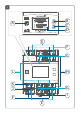
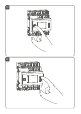
Start-up • • • • • • • • • Disconnect the power distribution panel from the mains (see figure 2) and, if necessary, cover any live parts (see safety rules). Remove the cover from the power distribution panel. Place the blind actuator onto the DIN rail (see figure 3). Make sure that you can read the letters on the device and display and that the connecting terminals of channel 1 and 2 are at the top.
Start-up the blinds down for the selected channel to the corresponding terminal ( ) (E) (see figure 6+7). The phase conductor connection is marked with an arrow pointing to the centre of the device, the switched phase conductor with an arrow pointing towards outside. To connect or loosen the conductor, the white actuation lever at the top of the clamp has to be pressed. The network terminals may be used only for connecting the power supply to the device or for connecting loads to the device.
Start-up After installation and before connecting the device to the app, simple operating functions (e.g. for test purposes) are available directly on the device (see “6 Operation” on page 50). 5.3 Teaching-in Read this entire section before starting the teach-in procedure. First set up your Homematic IP Access Point via the Homematic IP app to enable operation of other Homematic IP devices within your system. For further information, refer to the operating manual of the Access Point.
Operation • • phone. Select the menu item “Teach-in device”. After power supply is established, the teach-in mode will be active for 3 minutes. You can manually start the teach-in mode for another 3 minutes by pressing the system button (A) briefly (see figure 9). • • • • • • • 6 Your device will automatically appear in the Homematic IP app. To confirm, enter the last four digits of the device number (SGTIN) in your app or scan the QR code.
Operation • • • Channel button (B) Select button (C) External push-buttons/switches (H and L) System button By pressing the system button briefly (see figure 10), you can activate the LCD background light. Channel button By pressing the channel button briefly (see figure 11), you can select the desired channel. With each button press, 1 1 you can switch to the 1 1 next channel. The selected channel is indicated by the flashing symbol.
Operation Symbol Meaning Move down Moved up Stop Select button After selecting a channel via the ‘Channel’ button, you can select the output channel status by briefly pressing the ‘Select’ button (see figure 12) (move down - stop - move up - stop etc.). On each button press, you can switch to the next status. For the input channels, pressing the Select button simulates a short button press for the selected input channel. Connected actuators can be switched.
Operation Push-buttons: • Short button press button for channel 1, 3, 5, 7: The motor for the shutters/awnings moves down to the corresponding end position. • Short button press button for channel 2, 4, 6, 8: The motor for the shutters/awnings moves up to the corresponding end position. • Short button press opposite direction: The motor stops. • Long button press: The motor moves into the corresponding direction until the push-button is released or the end position of the shutter or awning is reached.
Troubleshooting 7 Troubleshooting 7.1 Error codes and flashing sequences Flashing code / Meaning LC display Solution Short orange flashing (every 10 s) Teach-in mode active Enter the last four numbers of the device serial number to confirm (see “5.3 Teaching-in” on page 49). 6x long red flashing Device defective Have a look at your app for error message or contact your retailer. 1x orange and 1 x green lighting Test display Once the test display has stopped, you can continue.
Troubleshooting 7.2 Command not confirmed If at least one receiver does not confirm a command, the device LED (A) lights up red at the end of the failed transmission process. The failed transmission may be caused by radio interference (see “11 Technical specifications” on page 58). The failed transmission may also be caused by the following: • Receiver cannot be reached. • Receiver is unable to execute the command (load failure, mechanical blockade, etc.). • Receiver is defective. 7.
Restore factory settings red lighting of the device LED (A) , and may manifest itself in the device temporarily working incorrectly. The device starts working correctly again after a short period (max. 1 hour). 8 Restore factory settings The factory settings of the device can be restored. If you do this, you will lose all your settings.
Maintenance and cleaning 9 Maintenance and cleaning The product does not require any maintenance. Enlist the help of an expert to carry out any maintenance or repairs. The mains voltage must be disconnected before the device is removed (trip the miniature circuitbreaker). Only qualified electricians (to VDE 0100) are permitted to carry out work on the 230 V mains. Clean the device using a soft, lint-free cloth that is clean and dry.
Technical specifications factors such as humidity in the vicinity have an important role to play, as do on-site structural/ screening conditions. Hereby, eQ-3 AG, Maiburger Str. 29, 26789 Leer/Germany declares that the radio equipment type Homematic IP HmIP-DRBLI4 is in compliance with Directive 2014/53/ EU. The full text of the EU declaration of conformity is available at the following internet address: www.homematic-ip.
Technical specifications Installation: Degree of protection: Ambient temperature: Dimensions (W x H x D): Weight: Radio frequency band: Maximum radiated power: Receiver category: Typ. open area RF range: Duty cycle: 0.75-2.5 mm² mounting rail (DIN rail) according to EN 60715 IP20 -5 to +40 °C 72 x 90 x 69 mm (4 WM width) 256 g 868.0-868.60 MHz 869.4-869.65 MHz 10 dBm SRD category 2 190 m < 1 % per h/< 10 % per h Subject to technical changes.
Technical specifications Instructions for disposal Do not dispose of the device with regular domestic waste! Electronic equipment must be disposed of at local collection points for waste electronic equipment in compliance with the Waste Electrical and Electronic Equipment Directive. Information about conformity The CE sign is a free trading sign addressed exclusively to the authorities and does not include any warranty of any properties. For technical support, contact your specialist dealer.
Kostenloser Download der Homematic IP App! Free download of the Homematic IP app! Bevollmächtigter des Herstellers: Manufacturer’s authorised representative: eQ-3 AG Maiburger Straße 29 26789 Leer / GERMANY www.eQ-3.