
User manual


Table Of Contents
- 1 Hinweise zur Anleitung
- 2 Gefahrenhinweise
- 3 Funktion und Geräteübersicht
- 4 Allgemeine Systeminformationen
- 5 Inbetriebnahme
- 6 Fehlerbehebung
- 7 Wartung und Reinigung
- 8 Allgemeine Hinweise zum Funkbetrieb
- 9 Technische Daten
- 1 Information about this manual
- 2 Hazard information
- 3 Function and device overview
- 4 General system information
- 5 Start-up
- 6 Troubleshooting
- 7 Maintenance and cleaning
- 8 General information about radio operation
- 9 Technical specifications
35
Start-up
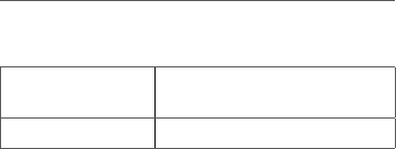
Permitted cable cross sections for connecting to the
switch actuator and meter are:
rigid cable [mm
2
] flexible cable without ferrule
[mm
2
]
1.5 – 2.50 1.5 – 2.50
5.2 Installation
You can install the switch actuator and meter
•
in a flush-mounting bo
x or
•
in a surface-mounting bo
x
.
5.2.1 Flush-mounting box installation
To install the switch actuator and meter in a flush-mount-
ing box, please proceed as follows:
• Switch o the fuse of the power circuit.
• Connect the actuator to L( D) and N (C) to obtain
power supply (see fig. 2).
• Route the switched phase (B) to the consumer
(see fig. 2).
• Fix the actuator to an appropriate flush-mounting
box. If required, you can remove the fixing lug (A).
• Close the flush-mounting box using an
appropriate cover.
• Switch the fuse of the power circuit on again, to
activate the teach-in mode of the device (see „5.3
Teaching-in“ on page 36).