OPERATOR’S MANUAL MANUEL D’UTILISATION MANUAL DEL OPERADOR ELECTRIC LOG SPLITTER FENDEUSE DE BÛCHES ÉLECTRIQUE PARTIDORA DE TRONCOS ELÉCTRICA UT49103 Your log splitter has been engineered and manufactured to our high standard for dependability, ease of operation, and operator safety. When properly cared for, it will give you years of rugged, trouble-free performance. WARNING: To reduce the risk of injury, the user must read and understand the operator’s manual before using this product.
See this fold-out section for all the figures referenced in the operator’s manual. Voir que cette section d’encart pour toutes les figures a adressé dans le manuel d’utilisation. Vea esta sección de la página desplegable para todas las figuras mencionó en el manual del operador. Fig. 3 Fig. 1 Fig.
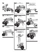
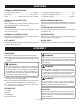
Fig. 7 Fig. 10 Fig. 13 RIGHT DRAINING OIL FROM OIL TANK (CORRECT, FORMA CORRECTA) (VIDANGER DE L’HUILE DU RÉSERVOIR HYDRAULIQUE) (OPERACIÓN DE DRENADO DEL ACEITE) A Fig. 8 A - Wood wedge (coin de bois, cuña de madera) RIGHT (CORRECT, FORMA CORRECTA) Fig. 11 Fig. 14 WRONG (MAL, INCORRECTO) Fig. 9 RESET BUTTON (BOUTON « RESET ») (BOTÓN DE REAJUSTE) A WRONG (MAL, INCORRECTO) A - Wood wedge (coin de bois, cuña de madera) Fig. 15 Fig.
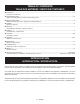
TABLE OF CONTENTS TABLE DES MATIÈRES / ÍNDICE DE CONTENIDO Introduction....................................................................................................................................................................... 2 Introduction / Introducción General Safety Rules......................................................................................................................................................
GENERAL SAFETY RULES WARNING: READ AND UNDERSTAND ALL INSTRUCTIONS. Failure to follow all instructions listed below, may result in electric shock, fire and/or serious personal injury. READ ALL INSTRUCTIONS KNOW YOUR POWER TOOL. Read the operator’s manual carefully. Learn the applications and limitations as well as the specific potential hazards related to this tool. GUARD AGAINST ELECTRICAL SHOCK BY PREVENTING BODY CONTACT WITH GROUNDED SURFACES.
GENERAL SAFETY RULES do not connect the equipment-grounding conductor to a live terminal. Repair or replace a damaged or worn cord immediately. Stay constantly aware of cord location and keep it well away from the rotating blade. TOOL SERVICE MUST BE PERFORMED ONLY BY QUALIFIED REPAIR PERSONNEL. Service or maintenance performed by unqualified p e r s o n a l c o u l d re s u l t i n a r i s k o f i n j u r y. INSPECT EXTENSION CORDS PERIODICALLY and replace if damaged.
SPECIFIC SAFETY RULES DO NOT ALLOW anyone to operate the log splitter who has not read the operator’s manual or has not been instructed on the safe use of the splitter. NEVER ALLOW CHILDREN OR UNTRAINED ADULTS TO OPERATE THIS MACHINE. LOGS TO BE SPLIT ON RAM-TYPE UNITS should be cut as squarely as possible. THE MACHINE OWNER should instruct anyone assisting him or her in safe log splitting operation.
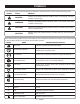
SYMBOLS The following signal words and meanings are intended to explain the levels of risk associated with this product. SYMBOL SIGNAL MEANING DANGER: Indicates an imminently hazardous situation, which, if not avoided, will result in death or serious injury. WARNING: Indicates a potentially hazardous situation, which, if not avoided, could result in death or serious injury. CAUTION: Indicates a potentially hazardous situation, which, if not avoided, may result in minor or moderate injury.
ELECTRICAL EXTENSION CORDS ELECTRICAL CONNECTION Use only 3-wire extension cords that have 3-prong grounding plugs and 3-pole receptacles that accept the tool's plug. When using a power tool at a considerable distance from the power source, use an extension cord heavy enough to carry the current that the tool will draw. An undersized extension cord will cause a drop in line voltage, resulting in a loss of power and causing the motor to overheat.
FEATURES PRODUCT SPECIFICATIONS Hydraulic Cylinder Pressure.................................. 2320 psi Oil Capacity................................................... 3.4 qts. (3.2 l) Input............................ 120 Volt, 60 Hz, AC Only, 15 Amps Log Capacity Diameter, maximum............................. 12 in. Log Capacity Diameter, minimum................................ 4 in. Log Capacity Length............................................... 20.5 in.
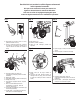
ASSEMBLY ASSEMBLING THE WHEELS See Figure 3. To attach the wheels to the base: n Locate the axle assembly; remove the hitch pin from the axle. n Lift the machine slightly and slip the axle into the wheel hole. n Next, slide the washer onto the axle. Still lifting the machine, slide the axle/wheel/washer combination into the wheel mounting hole in the machine base as shown in figure 3. n Slide the washer onto the axle. Push the hitch pin into the hole on the end of the axle to secure the wheel assembly.
OPERATION STARTING THE LOG SPLITTER See Figures 6 - 7. n Operator should be positioned at the rear of the log splitter as shown in figure 7. n Place the left hand on the hydraulic control lever and the right hand on the on/off switch. n Push down and hold the on/off switch. n While continuing to hold down the on/off switch, push down and hold the hydraulic control lever. NOTE: Both hands are required to start this product. The combination of both steps starts the ram which pushes the log into the wedge.
MAINTENANCE REPLACING HYDRAULIC OIL WARNING: When servicing, use only identical replacement parts. Use of any other parts may create a hazard or cause product damage. WARNING: Always wear eye protection with side shields marked to comply with ANSI Z87.1. Failure to do so could result in objects being thrown into your eyes, resulting in possible serious injury. GENERAL MAINTENANCE Avoid using solvents when cleaning plastic parts.
TROUBLESHOOTING PROBLEM POSSIBLE CAUSE SOLUTION Motor fails to start Overload Protection Device is disengaged to protect the log splitter from being damaged. Push reset button. See Figure 14. Won’t split logs Log is improperly positioned. Refer to Operation section for log loading. The size or hardness of the log exceeds the machine’s capacity. Reduce the log size before splitting. Wedge cutting edge is blunt. Refer to Sharpening Wedge in the Maintenance section. Oil leaks. Locate leak(s).
WARRANTY LIMITED WARRANTY STATEMENT Homelite Consumer Products, Inc., (“Homelite”) warrants to the original retail purchaser that this HOMELITE brand outdoor product is free from defect in material and workmanship and agrees to repair or replace, at Homelite’s, discretion, any defective product free of charge within these time periods from the date of purchase.
RÈGLES DE SÉCURITÉ GÉNÉRALES AVERTISSEMENT : Lire et veiller à bin comprendre toutes les instructions. Le non respect de toutes les instructions ci-dessous peut entraîner un choc électrique, un incendie et / ou des blessures graves. LIRE TOUTES LES INSTRUCTIONS PORTER UNE TENUE APPROPRIÉE. Ne pas porter de vêtements amples, cravates, ou bijoux susceptibles de se prendre et vous entraîner dans les pièces mobiles.
RÈGLES DE SÉCURITÉ GÉNÉRALES PORTER UNE PROTECTION RESPIRATOIRE. Porter un masque facial ou respiratoire si le travail produit de la poussière. RESTER VIGILANT ET GARDER LE CONTRÔLE. Se montrer attentif et faire preuve de bon sens. Ne pas utiliser l’outil en état de fatigue. Ne pas se presser. PORTER UNE PROTECTION AUDITIVE. Porter une protection auditive durant les périodes d’utilisation prolongée. NE PAS UTILISER L’OUTIL SI LE COMMUTATEUR NE PERMET PAS DE LE METTRE EN MARCHE OU DE L’ARRÊTER.
RÈGLES DE SÉCURITÉ PARTICULIÈRES NE PAS LAISSER quiconque n’ayant pas lu le manuel d’utilisation ou reçu des instructions adéquates sur la sécurité, utiliser la fendeuse. NE JAMAIS LAISSER DES ENFANTS OU DES ADULTES N’AYANT PAS REÇU LES INSTRUCTIONS APPROPRIÉES UTILISER LA MACHINE. SI QUELQU’UN AIDE au chargement des bûches à fendre, NE PAS mettre la machine en marche avant que cette personne se soit éloignée. NE JAMAIS LAISSER QUICONQUE MONTER SUR LA MACHINE.
SYMBOLES Les termes de mise en garde suivants et leur signification ont pour but d’expliquer le degré de risques associé à l’utilisation de ce produit. SYMBOLE SIGNAL SIGNIFICATION DANGER : Indique une situation extrêmement dangereuse qui, si elle n’est pas évitée, aura pour conséquences des blessures graves, voire mortelles. AVERTISSEMENT : Indique une situation potentiellement dangereuse qui, si elle n’est pas évitée, aura pour conséquences des blessures graves ou mortelles.
CARACTÉRISTIQUES ÉLECTRIQUES CORDONS PROLONGATEURS CONNEXION ÉLECTRIQUE Utiliser exclusivement des cordons prolongateurs à 3 fils doté d’une fiche à prise de terre branchés sur une prise triphasée compatible avec la fiche de l’outil. Lors de l’utilisation d’un outil électrique à grande distance d’une prise secteur, veiller à utiliser un cordon prolongateur d’une capacité suffisante pour supporter l’appel de courant de l’outil.
CARACTÉRISTIQUES FICHE TECHNIQUE Pression du vérin hydraulique.............................. 2 320 psi Contenance en huile................................. 3,2 l (3,4 quarts) Capacité maximum de diamètre de bûche.....................................................305 mm (12 po) Alimentation..................120 V, 60 Hz, CA seulement, 15 A Capacité minimum de diamètre de bûche...102 mm (4 po) Capacité de longueur de bûche..............
ASSEMBLAGE FIXATION DE ROUES AVERTISSEMENT : Ne pas brancher sur le secteur avant d’avoir terminé l’assemblage. Le non respect de cet avertissement peut causer un démarrage accidentel, entraînant des blessures graves. ATTENTION : Ne pas desserrer la vis de purge avant d’utiliser la machine peut causer la rupture des joints du circuit hydraulique. La rupture des joints peut entraîner des dommages permanents à la fendeuse. Voir la figure 3.
UTILISATION MISE EN MARCHE DE LA FENDEUSE Voir les figures 6 et 7. n L’opérateur doit toujours se tenir à l’arrière de la fendeuse, comme le montre la figure 7. n Placer la main gauche sur le levier de commande hydraulique et la main droite sur le commutateur marche / arrêt. n Maintenir le commutateur enfoncé. n Tout en maintenant le commutateur enfoncé, abaisser le levier de commande hydraulique et le maintenir dans cette position.
ENTRETIEN CHANGEMENT DE L’HUILE HYDRAULIQUE AVERTISSEMENT : Voir les figures 12 et 13. Utiliser exclusivement des pièces d’origine pour les réparations. L’usage de toute autre pièce pourrait créer une situation dangereuse ou endommager l’outil. L’huile hydraulique de la fendeuse doit être changée toutes les 150 heures d’utilisation. n Débrancher la fendeuse. n Positionner la fendeuse de façon à ce que le moteur soit légèrement plus élevé que le bouchon de vidange d’huile.
DÉPANNAGE PROBLÈME CAUSE POSSIBLE SOLUTION Le moteur ne démarre pas Le dispositif de protection contre l e s s u r c h a rg e s s u s c e p t i b l e s d’endommager la machine est désengagé. Sur le bouton de réarmement. Voir la figure 14. La machine ne fend pas les bûches La bûche n’est pas correctement positionnée. Consulter la section Utilisation pour le chargement des bûches. La taille ou la dûreté de la bûche est supérieure à la capacité de la machine.
GARANTIE Homelite Consumer Products, Inc. (« Homelite ») garantit à l’acheteur original au détail que ce produit de plein air de marque HOMELITE est exempt de tout vice de matériau ou de fabrication et s’engage à réparer ou remplacer, à discrétion, tout produit s’avérant défectueux au cours des périodes indiquées ci-dessous, à compter de la date d’achat. B.
REGLAS DE SEGURIDAD GENERALES ADVERTENCIA: LEA Y COMPRENDA TODAS LAS INSTRUCCIONES. El incumplimiento de las instrucciones señaladas abajo puede causar descargas eléctricas, incendios y lesiones serias. LEA TODAS LAS INSTRUCCIONES FAMILIARÍCESE CON SU HERRAMIENTA ELÉCTRICA. Lea cuidadosamente el manual del operador. Aprenda los usos, limitaciones y posibles peligros relacionados con esta herramienta. PROTÉJASE CONTRA DESCARGAS ELÉCTRICAS EVITANDO TOCAR CON EL CUERPO SUPERFICIES CONECTADAS A TIERRA.
REGLAS DE SEGURIDAD GENERALES AVANCE LA PIEZA DE TRABAJO EN LA DIRECCIÓN CORRECTA. Solamente empuje la pieza de trabajo hacia la hoja, fresa o tambor de lijado, contra el sentido de rotación de éstos. PERMANEZCA ALERTA Y EN CONTROL. Preste atención a lo que esté haciendo y aplique el sentido común. No utilice la herramienta cuando esté cansado. No se apresure. NUNCA DEJE FUNCIONANDO DESATENDIDA LA HERRAMIENTA. APAGUE LA CORRIENTE. No abandone la herramienta hasta verla completamente detenida.
REGLAS DE SEGURIDAD ESPECÍFICAS NO PERMITA que utilice la partidora de troncos ninguna persona que no haya leído el manual del operador y que no haya recibido instrucciones sobre la forma de usar la partidora con seguridad. AQUELLOS TRONCOS QUE VAYAN A PARTIRSE EN UNIDADES DE ARIETE deben cortarse tan a escuadra como sea posible. NUNCA PERMITA QUE UTILICEN ESTA MÁQUINA NIÑOS NI ADULTOS CARENTES DE LA DEBIDA INSTRUCCIÓN PARA SU MANEJO.
SÍMBOLOS Las siguientes palabras de señalización y sus significados tienen el objeto de explicar los niveles de riesgo relacionados con este producto. SÍMBOLO SEÑAL SIGNIFICADO PELIGRO: Indica una situación peligrosa inminente, la cual, si no se evita, causará lesiones graves o mortales. ADVERTENCIA: Indica una situación peligrosa posible, la cual, si no se evita, podría causar lesiones graves o mortales.
ASPECTOS ELÉCTRICOS CORDONES DE EXTENSIÓN CONEXIÓN ELÉCTRICA Sólo utilice cordones de extensión de 3 conductores con clavijas de 3 patillas y receptáculos de 3 polos que acepten la clavija del cordón de la herramienta. Al utilizar una herramienta eléctrica a una distancia considerable del suministro de corriente, asegúrese de utilizar un cordón de extensión del grueso suficiente para soportar el consumo de corriente de la herramienta.
CARACTERÍSTICAS ESPECIFICACIONES DEL PRODUCTO Presión del cilindro hidráulico.............................. 2 320 psi Capacidad de aceite............................... 3,2 l (3,4 cuartos) Corriente de entrada...... 120 V, 60 Hz, sólo corr. alt., 15 A Capacidad de troncos, diámetro máximo............................... 305 mm (12 pulg.) Capacidad de troncos, diámetro mínimo............................... 102 mm (4 pulg.) Capacidad de troncos, longitud.......... 521 mm (20,5 pulg.
ARMADO ACOPLAMIENTO DE RUEDA ADVERTENCIA: No conecte la unidad al suministro de corriente sin haber terminado de armarla. De lo contrario la unidad puede ponerse en marcha accidentalmente, con el consiguiente riesgo de lesiones corporales serias. Vea la figura 3. Para acoplar las ruedas a la base de la lavadora a presión: n Idenitfique el conjunto del eje; retire el pasador de enganche del eje. n Levante levemente la máquina y deslice el eje en el orificio de la rueda.
FUNCIONAMIENTO Para revisar el nivel de aceite: n Desconecte la partidora de troncos. n Con el mango de levantamiento ponga en posición vertical la partidora de troncos sobre el extremo donde están las ruedas (vea la figura 12). n Con una llave hexagonal de 8 mm retire el perno de drenaje de aceite, y limpie con un paño la varilla del nivel del aceite. n Limpie la varilla del nivel del aceite y vuelva a introducirla en el tanque de aceite.
MANTENIMIENTO REEMPLAZO DEL ACEITE HIDRÁULICO ADVERTENCIA: Al dar servicio a la unidad, sólo utilice piezas de repuesto idénticas. El empleo de piezas diferentes puede causar un peligro o dañar el producto. Vea las figuras 12 y 13. El aceite hidráulico de la partidora de troncos debe cambiarse cada 150 horas de uso. n Desconecte la partidora de troncos. n Acomode la partidora de manera que el extremo del motor quede a un nivel levemente arriba del tapón de drenaje de aceite.
SOLUCIÓN DE PROBLEMAS PROBLEMA CAUSA POSIBLE SOLUCIÓN El motor no arranca El dispositivo de protección contra sobrecarga está desacoplado para proteger de daños la partidora de troncos. Oprima el botón de readjuste. Vea la figura 14. No se parten los troncos Está mal acomodado el tronco. Consulte la sección Funcionamiento para todo lo relacionado con la colocación de los troncos. El tamaño o la dureza del tronco excede la capacidad de la máquina. Reduzca el tamaño del tronco antes de partirlo.
GARANTÍA DECLARACIÓN DE LA GARANTÍA LIMITADA Homelite Consumer Products, Inc. garantiza al comprador original al menudeo que este producto para uso en el exterior HOMELITE carece de defectos en materiales y mano de obra y acuerda reparar o reemplazar, a la sola discreción de Homelite, cualquier producto defectuoso sin cargo alguno dentro del plazo establecido después de la fecha de compra.
ELECTRIC LOG SPLITTER OPERATOR’S MANUAL MANUEL D’UTILISATION MANUAL DEL OPERADOR FENDEUSE DE BÛCHES ÉLECTRIQUE / PARTIDORA DE TRONCOS ELÉCTRICA UT49103 SERVICE For parts or service, contact your nearest Homelite authorized service dealer. Be sure to provide all relevant information when you call or visit. For the location of the authorized service dealer nearest you, please call 1-800-242-4672 or visit us online at www.homelite.com.