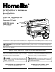
OPERATOR’S MANUAL Manuel de l’opérateur Manuel d’utilisation Manual del operador 5700 WATT GENERATOR Générateur de 5,700 watts Generador 5700 watts HG5700 Series Série HG5700 Serie HG5700 ON OFF Your generator has been engineered and manufactured to our high standard for dependability, ease of operation, and operator safety. When properly cared for, it will give you years of rugged, trouble-free performance.
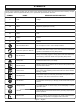
TABLE OF CONTENTS Introduction..................................................................................................................................................................... 2 Important Safety Instructions......................................................................................................................................3-4 Specific Safety Rules...................................................................................................................
important safety instructions Keep all bystanders, children, and pets at least 10 feet away. DANGER: Carbon Monoxide. Using a generator indoors will KILL YOU IN MINUTES. Wear sturdy and dry shoes or boots. Do not operate while barefoot. Generator exhaust contains high levels of carbon monoxide (CO), a poisonous gas you cannot see or smell. If you can smell the generator exhaust, you are breathing CO. But even if you cannot smell the exhaust, you could be breathing CO.
important safety instructions Maintain the unit per maintenance instructions in this Operator’s Manual. Inspect the unit before each use for loose fasteners, fuel leaks, etc. Replace damaged parts. SPECIFIC SAFETY RULES WARNING: When this generator is used to supply a building wiring system: generator must be installed by a qualified electrician and connected to a transfer switch as a separately derived system in accordance with NFPA 70, National Electrical Code.
SYMBOLS Some of the following symbols may be used on this product. Please study them and learn their meaning. Proper interpretation of these symbols will allow you to operate the product better and safer. SYMBOL NAME DESIGNATION/EXPLANATION V Volts Voltage A Amperes Current Hz Hertz Frequency (cycles per second) W Watt Power hrs Hours Time gal Gallon Volume qt Quart Volume Wet Conditions Alert Do not expose to rain or use in damp locations.
SYMBOLS The following signal words and meanings are intended to explain the levels of risk associated with this product. SYMBOL SIGNAL MEANING DANGER: Indicates an imminently hazardous situation, which, if not avoided, will result in death or serious injury. WARNING: Indicates a potentially hazardous situation, which, if not avoided, could result in death or serious injury. CAUTION: Indicates a potentially hazardous situation, which, if not avoided, may result in minor or moderate injury.
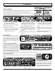
symbols SAFETY LABELS The information below can be found on the generator. For your safety, please study and understand all of the labels before starting the generator. If any of the labels come off the unit or become hard to read, contact an authorized service center for replacement. You WILL be KILLED or SERIOUSLY HURT if you do not follow the Operator’s Manual instructions. Risk of Fire. Do not add fuel while the product is operating. Generator is a potential source of electric shock.
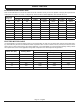
electrical extension cord cable size Refer to the table below to ensure the cable size of the extension cords you use are capable of carrying the required load. Inadequate size cables can cause a voltage drop, which can burn out the appliance and overheat the cord. Load in Watts Current in Amperes At 120V At 240V 2.5 300 5 Maximum Allowable Cord Length #8 Wire #10 Wire #12 Wire #14 Wire #16 Wire 600 1000 ft. 600 ft. 375 ft. 250 ft. 600 1200 500 ft. 300 ft. 200 ft. 125 ft. 7.
electrical generator Capacity Make sure the generator can supply enough continuous (running) and surge (starting) watts for the items you will power at the same time. Follow these simple steps. 1. Select the items you will power at the same time. 2. Total the continuous (running) watts of these items. This is the amount of power the generator must produce to keep the items running. See the wattage reference chart at right. 3. Estimate how many surge (starting) watts you will need.
FEATURES PRODUCT SPECIFICATIONS Engine Engine Type................................................... 4 Stroke, OHV Cooling System....................................................Forced Air Starting System.......................................................... Recoil Ignition System.............................................................T.C.I. Spark Plug......................................................NGK BPR4ES Engine Lubricant Volume...........................................1.1 qt.
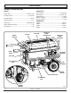
FEATURES KNOW YOUR GENERATOR ground terminal See Figure 1. The safe use of this product requires an understanding of the information on the product and in this operator’s manual as well as a knowledge of the project you are attempting. Before use of this product, familiarize yourself with all operating features and safety rules. The ground terminal is used to assist in properly grounding the generator to help protect against electrical shock.
loose parts list The following items are included with the generator: 7 1 8 6 5 9 2 14 10 3 13 11 12 4 15 16 Key No. 1 2 3 4 5 6 7 8 9 Description Qty. Bolt (3/8-16 x 4-1/4 in.)........................................2 Washer (3/8 in.).....................................................6 Spacer (.38 ID)......................................................2 Wheel....................................................................2 Lock Nut (3/8-16)............................................
ASSEMBLY UNPACKING This product requires assembly. bolt Carefully cut the box down the sides then remove the machine and any accessories from the box. Make sure that all items listed in the packing list are included. NOTE: This machine is heavy and requires a minimum of two people to lift. To avoid back injury, lift with your legs and not your back. Inspect the unit carefully to make sure no damage occurred during shipping.
assembly installing the wheels See Figure 3. Wheels are provided to assist in moving the generator to the desired location and should be installed on the side opposite the handle. Locate the following items: 2 bolts (3/8-16 x 4-1/4 in.) 6 washers (3/8 in.) 2 spacers (.38 ID) 2 wheels 2 lock nuts (3/8-16) Raise the end of the generator opposite the handle high enough to gain access to the frame bottom; securely position props underneath to support.
operation BEFORE OPERATING the UNIT DANGER: Carbon Monoxide. Using a generator indoors will KILL YOU IN MINUTES. Generator exhaust contains high levels of carbon monoxide (CO), a poisonous gas you cannot see or smell. If you can smell the generator exhaust, you are breathing CO. But even if you cannot smell the exhaust, you could be breathing CO. Never use a generator inside homes, garages, crawlspaces, or other partly enclosed areas. Deadly levels of carbon monoxide can build up in these areas.
operation checking/adding fuel fuel cap See Figure 7. Remove the fuel cap. fuel tank engine switch Fill the fuel tank to 1 in. below the top of the fuel neck. Replace and secure the fuel cap. NOTE: Always use unleaded gasoline with a pump octane rating of 86 or higher. Never use old, stale, or contaminated gasoline, and do not use an oil/gas mixture. Do not allow dirt or water into the fuel tank. using fuel stabilizer Fuel gets old, oxidizes, and breaks down over time.
operation NOTE: Do not allow the grip to snap back after starting; return it gently to its original place. Allow the engine to run for 30 seconds, then move the choke lever left to the RUN position. Stopping the engine See Figures 8 - 9. To stop the engine under normal operating conditions: Remove any load from the generator. Turn the fuel valve to the OFF position. Put the engine switch in the OFF ( O ) position.
maintenance Replace the element in the air filter unit. Replace the air filter cover and tighten screws to secure. air filter cover NOTE: Do not run the generator without the air filter. Rapid engine wear will result. changing engine lubricant See Figure 12. Remove the oil cap/dipstick. Place a container underneath the oil drainage bolt to collect used lubricant as it drains. Unscrew the oil drainage bolt and remove. Allow lubricant to drain completely.
MAINTENANCE CLEANING THE EXHAUST PORT AND MUFFLER Depending on the type of fuel used, the type and amount of lubricant used, and/or your operating conditions, the exhaust port and muffler may become blocked with carbon deposits. If you notice a power loss with your gas-powered products, you may need to remove these deposits to restore performance. We highly recommend that only qualified service technicians perform this service. spark arrestor See Figure 14. Inspect the spark arrestor for breaks or holes.
MAINTENANCE storage When preparing the generator for storage, allow the unit to cool completely then follow the guidelines below. storage time prior to storing Less than 2 months Drain gasoline from tank and dispose of in a suitable container according to state and local ordinances. 2 months to 1 year Drain fuel from carburetor. Drain gasoline from tank and dispose of in a suitable container according to state and local ordinances. 1 year or more Drain fuel from the carburetor.
troubleshooting PROBLEM POSSIBLE CAUSE Engine will not start. Engine switch is off. No fuel. Lubricant level is low. Engine lacks power. Fuel element clogged. AC receptacle does not work. Circuit breaker is off. Item plugged in is defective. SOLUTION Turn engine switch to ON. Fill fuel tank. Check engine lubrincant level and fill, if necessary. Fuel valve is off. Turn fuel valve on. Spark plug faulty, fouled, or improperly Replace spark plug. gapped. Choke lever is in RUN position.
WARRANTY LIMITED WARRANTY WARRANTY COVERAGE Homelite Consumer Products, Inc.
WARRANTY Yamaha Motor Corporation USA Spark Ignited Small Off-Road Equipment (SORE) Limited and EPA Emissions Warranty Yamaha Motor Corporation, USA, hereby warrants that new Yamaha Spark Ignited Small Off Road Engines, hereafter called SORE engines, purchased from an authorized Yamaha SORE engine dealer in the continental United States will be free from defects in material and workmanship for the period of time stated herein, subject to certain stated limitations.
5700 WATT GENERATOR OPERATOR’S MANUAL Générateur de 5,700 watts Generador 5700 watts HG5700 Series MANUEL D’UTILISATION MANUAL DEL OPERADOR WARNING: The engine exhaust from this product contains chemicals known to the State of California to cause cancer, birth defects, or other reproductive harm. CALIFORNIA PROPOSITION 65 Série HG5700 Serie HG5700 SERVICE For parts or service, contact your nearest Homelite authorized service dealer. Be sure to provide all relevant information when you call or visit.