OPERATOR’S MANUAL BACKPACKER II UT08072 and UT08572 Your blower has been engineered and manufactured to Homelite’s high standard for dependability, ease of operation, and operator safety. When properly cared for, it will give you years of rugged, trouble-free performance. WARNING: To reduce the risk of injury, the user must read and understand the operator's manual before using this product. Thank you for buying a Homelite product.
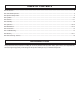
TABLE OF CONTENTS n Introduction ..................................................................................................................................................................... 2 �n General Safety Rules ....................................................................................................................................................... 3 �n Specific Safety Rules.............................................................................................................
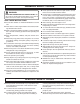
GENERAL SAFETY RULES n Never operate the unit without a spark arrestor screen; this screen is located inside the muffler. WARNING: n Product users on United States Forest Service land, and in some states, must comply with fire prevention regulations. This product is equipped with a spark arrestor; however, other user requirements may apply. Check with the federal, state, or local authorities in your area. READ AND UNDERSTAND ALL INSTRUCTIONS.
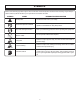
SYMBOLS Some of the following symbols may be used on this tool. Please study them and learn their meaning. Proper interpretation of these symbols will allow you to operate the tool better and safer. SYMBOL NAME DESIGNATION/EXPLANATION Safety Alert Precautions that involve your safety. Read The Operator’s Manual To reduce the risk of injury, user must read and understand operator’s manual before using this product.
SYMBOLS The following signal words and meanings are intended to explain the levels of risk associated with this product. SYMBOL SIGNAL MEANING DANGER: Indicates an imminently hazardous situation, which, if not avoided, will result in death or serious injury. WARNING: Indicates a potentially hazardous situation, which, if not avoided, could result in death or serious injury. CAUTION: Indicates a potentially hazardous situation, which, if not avoided, may result in minor or moderate injury.
FEATURES PRODUCT SPECIFICATIONS Weight ....................................................................................................................................................................... 14.7 lbs. Engine displacement ....................................................................................................................................................... 30cc Air Velocity: MPH.....................................................................................................
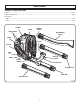
FEATURES KNOW YOUR BLOWER THROTTLE TRIGGER See Figure 1. Before attempting to use this product, familiarize yourself with all operating features and safety rules. The blower can be operated at any speed between idle and full throttle. TRIGGER LOCK BLOWER TUBES The trigger lock feature is used for easier starting and also allows the user to operate the blower without holding the throttle trigger. To disengage the trigger lock, simply depress the throttle trigger.
ASSEMBLY THROTTLE CONTROL HANDLE THROTTLE CABLE WARNING: Disconnect the spark plug wire before assemblying parts. Failure to do so could result in possible serious personal injury. ASSEMBLING THE BLOWER TUBES See Figures 2 - 5. n Place large clamp on the elbow tube and install the elbow tube onto blower. Tighten large clamp securely. UPPER TUBE WING NUT n Place large clamp on the bellows and install the bellows onto the elbow. Tighten clamp securely. n Insert upper tube into throttle control handle.
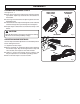
ASSEMBLY ASSEMBLING HARNESS STRAPS SHORT LOOPED END OF STRAP See Figures 6 - 7. n Place short looped end of the harness strap through the top bracket. Open loop and slide onto extruded end of the bracket. EXTRUDED END OF BRACKET n Lace long end of the harness strap through the slot in the backpack frame. n Thread the harness strap end through the center of buckle and then through the top toothed portion and tighten. n Repeat steps to attach the second harness strap to the blower.
OPERATION FILLING THE TANK WARNING: WARNING: Do not allow familiarity with tools to make you careless. Remember that a careless fraction of a second is sufficient to inflict serious injury. Always stop the engine before filling the fuel tank. Never add fuel to a machine with a running or hot engine. Move at least 30 ft. from the refueling area before starting engine. Do not smoke while filling the tank. WARNING: �n Clean the surface around the fuel cap to prevent contamination.
OPERATION STARTING AND STOPPING See Figures 8 - 9. TO START: n Place the blower on a flat, bare surface. THROTTLE TRIGGER �n Disengage the trigger lock. n Push the primer bulb, slowly, 7 times. n Do not engage the handle while starting. n Set choke to START position. TRIGGER LOCK n Pull the starter handle until the engine runs. n Allow the engine to run 15 seconds, then engage the trigger to operate SWITCH Fig. 8 TO STOP: PRIMER BULB Release the trigger and press STOP ( O ) until the engine stops.
OPERATION n Conserve water by using power blowers instead of hoses for many lawn and garden applications, including areas such as gutters, screens, patios, grills, porches, and gardens. n Use the nozzle for larger volume, so the air stream can work close to the ground. n After using blowers or other equipment, CLEAN UP! Dispose of debris properly. n Watch out for children, pets, open windows, or freshly washed cars, and blow debris safely away.
MAINTENANCE SPARK ARRESTOR The fuel cap contains a non-serviceable filter and a check valve. A clogged fuel filter will cause poor engine performance. If performance improves when the fuel cap is loosened, the check valve may be faulty or filter clogged. Replace the fuel cap if required. The muffler is equipped with a spark arrestor screen inside the muffler body. After extended use the screen can become dirty; you may need to have the muffler replaced by an authorized servicing dealer.
TROUBLESHOOTING IF THESE SOLUTIONS DO NOT SOLVE THE PROBLEM CONTACT YOUR AUTHORIZED SERVICING DEALER. PROBLEM POSSIBLE CAUSE SOLUTION Engine will not start. 1. No spark. 1. Check spark. Remove spark plug. Reattach the spark plug cap and lay spark plug on metal cylinder. Pull the starter rope and watch for spark at spark plug tip. If there is no spark, repeat test with a new spark plug. 2. No fuel. 2. Push primer bulb until fuel is visible in the bulb.
WARRANTY LIMITED WARRANTY STATEMENT In addition, this warranty does not cover: A. Tune-ups – Spark Plugs, Carburetor, Carburetor Adjustments, Ignition, Filters B.
WARRANTY THE FOLLOWING CALIFORNIA AIR RESOURCES BOARD (CARB) STATEMENT ONLY APPLIES TO MODEL NUMBERS REQUIRED TO MEET THE CARB REQUIREMENTS. HOMELITE CONSUMER PRODUCTS, INC., LIMITED WARRANTY FEDERAL AND CALIFORNIA EMISSION CONTROL SYSTEMS NONROAD AND SMALL OFF-ROAD ENGINES The U.S. Environmental Protection Agency (EPA), the California Air Resources Board (CARB), and Homelite Consumer Products, Inc. are pleased to explain the Emission Control System Warranty on your nonroad or small off-road engine.
WARRANTY THIS PRODUCT WAS MANUFACTURED WITH A CATALYST MUFFLER Congratulations! You have made an investment toward protecting the environment. In order to maintain this product’s original emission level, please refer to the maintenance section below. EMISSIONS MAINTENANCE SCHEDULE AND WARRANTED PARTS LIST Emissions Parts Inspect Before Each Use Clean Every 5 Hours Replace Every 25 Hours or Yearly Clean Every 25 Hours or Yearly Replace Every 50 Hours CATALYTIC MUFFLER ASSEMBLY .........................
OPERATOR’S MANUAL BACKPACKER II UT08072 and UT08572 WARNING: The engine exhaust from this product contains chemicals known to the State of California to cause cancer, birth defects, or other reproductive harm. CALIFORNIA PROPOSITION 65 SERVICE For parts or service, contact your nearest Homelite authorized service dealer. Be sure to provide all relevant information when you call or visit. For the location of the authorized service dealer nearest you, please call 1-800-242-4672 or visit us online at www.