Home Wireless Networks™ HWN500 Network Reference Manual (working copy) 35(/,0,1$5< Y Printed 11/6/98
Note: Record your Controller serial number and system password on the lines below. You will need the Controller serial number during the system set-up procedure (see page 14 for information on locating the Controller serial number). You will need the system password in order to make changes to the system set-up (see page 64for information on the system password).
Contents Before you begin . . . . . . . . . . . . . . . . . . . . . . . . . . . . . . . . 6 Overview . . . . . . . . . . . . . . . . . . . . . . . . . . . . . . . . . . . . . . . 6 About system security . . . . . . . . . . . . . . . . . . . . . . . . . . . 7 Network components . . . . . . . . . . . . . . . . . . . . . . . . . . . . 7 Installation sequence . . . . . . . . . . . . . . . . . . . . . . . . . . . . . . 9 Safety instructions . . . . . . . . . . . . . . . . . . . . . . . . . . . . . . . .
Attaching rubber feet to charging cradle . . . . . . . . . . . . . . Installing the battery pack . . . . . . . . . . . . . . . . . . . . . . . . . Charging the Handset battery . . . . . . . . . . . . . . . . . . . . . . Registering a Handset with the Controller . . . . . . . . . . . . . Self-registration . . . . . . . . . . . . . . . . . . . . . . . . . . . . . . . Establishing dialing rules . . . . . . . . . . . . . . . . . . . . . . . . . . 31 32 33 34 35 41 Installing Phone Jacks . . . . . . . . . . .
Dropping out of a Conference Call . . . . . . . . . . . . . . . . . Dropping another member from a Conference Call . . . . Miscellaneous General Features . . . . . . . . . . . . . . . . . . . . Adjusting the Handset Volume . . . . . . . . . . . . . . . . . . . . Adjusting the Ringer Volume . . . . . . . . . . . . . . . . . . . . . Scrolling through the menus. . . . . . . . . . . . . . . . . . . . . . Locating a misplaced handset . . . . . . . . . . . . . . . . . . . . Phone Company Calling Features . . . .
Behind a PBX or Key System . . . . . . . . . . . . . . . . . . . . Viewing access code settings . . . . . . . . . . . . . . . . . . Defining an access code . . . . . . . . . . . . . . . . . . . . . . Setting System Timers . . . . . . . . . . . . . . . . . . . . . . . . . . . Setting the Hold Recall Timer . . . . . . . . . . . . . . . . . . . . Setting the Transfer Recall Timer . . . . . . . . . . . . . . . . . Setting voice mail options . . . . . . . . . . . . . . . . . . . . . . . . . Line Setup . . . . .
Wall Mounting Instructions . . . . . . . . . . . . . . . . . . . . . . 101 Mounting the Controller on a wall. . . . . . . . . . . . . . . . . . . 101 Mounting the Handset charging cradle on a wall . . . . . . .
Before you begin Overview Your Home Wireless Networks™ integrated communications system is the world’s first wireless networking product designed to provide both voice and data networking capabilities to the home and small business. No additional phone lines to run! With the Home Wireless Networks system, you can easily build a wireless network that includes PCs, wireless handsets, standard telephones, fax machines, modems, etc.
About system security Your Home Wireless Networks communications system uses direct sequence spread spectrum technology to help ensure secure communications. (Stuckey to provide verbiage.) A system password is also used to help prevent unauthorized individuals from registering a handset or other device on your network. Note: You should change the default system password to one of your own choosing after adding the first Data Jack or Handset to the system.
Data Jack The Data Jack allows you to wirelessly connect a PC to your Home Wireless Networks communications system. By adding several PCs to the network, you can build a wireless Local Area Network (LAN) that allows you to share files, printers, modems, Internet account, etc. between the networked PCs. Connecting a PC to the network via a Data Jack also allows you to perform system administration tasks from the PC. Handset The Handset is an advanced wireless display telephone.
Installation sequence Network components must be installed in the following order: 1. Controller (see page 13); 2. Data Jack (see page 25) or Handset (see page 30); 3. Phone Jacks (see page 45). Safety instructions When using your telephone equipment, basic safety precautions should always be followed to reduce the risk of fire, electric shock, and injury. 1. Read and understand all instructions. 2. Follow all warnings and instructions marked on the product. 3.
the type of power that is supplied to your location, consult your dealer or local power company. 7. Do not overload the wall outlets or extension cords as this can result in the risk of fire or electric shock. 8. Do not allow anything to rest on the power cord. Do not locate this product where the cord will be abused by people walking on it. 9. This product must not be installed in an attic, garage or other temperature-extreme environment. 10.
Battery cautions To reduce the risk of fire or injury to persons caused by batteries, read and follow these instructions. 1. Use only the proper type and size batteries. 2. Do not dispose of batteries in a fire. The cell may explode. Check with local codes for possible special disposal instructions. 3. Do not open or mutilate the battery. Released electrolyte is corrosive and may cause damage to eyes or skin. It may be toxic if swallowed. 4.
Notice regarding line intereference Connecting equipment not produced by Home Wireless Networks to a line used by the Controller may cause interference with the network under the following circumstances: • When the non-Home Wireless Networks device is in use and a wireless network device attempts to use the same line, the Controller may not be able to acquire the line for the wireless device.
Installing the Controller Checking parts The Controller kit should contain the following parts: • • • • • Controller Transformer 9V Battery 6’ RJ-14 Cables (2) Rubber mounting feet If any parts are missing or broken, call your dealer. Controller Installation Sequence Use the following steps to install the Controller. 1. Record the Controller serial number. 2. Choose a location for the Controller. 3. Attach protective rubber feet to Controller base (unless wall-mounting the Controller). 4.
6. Connect the power. 7. Connect a wired device to Controller EJack (optional). Recording the Controller Serial Number Before you begin installing your Controller, be sure to record the unit’s serial number in the space provided on the inside front cover of this manual. You will need this information in order to add the first handset or data or phone jack to the network. The Controller serial number is located on the inside top surface of the Controller. It can be found by removing the Controller cover.
M odel: 95-005-000 SN: 9 843001 Locating the Controller serial number Choosing a location The Controller can be placed either on a horizontal service such as a desk or counter top, or it can be wall-mounted. Remember the following points when deciding where to install the Controller. • The Controller must be placed in an easily-accessible location to facilitate battery replacement. • The Controller should be either wallmounted or placed on a stable horizontal surface such as a desk or countertop.
• The Controller must be located within 6 feet of an electrical outlet that is not controlled by a wall switch, and within 6 feet of a telephone jack or jacks that contain all the telephone lines coming into your home. Note: If there is no single location where all telephone lines are present in the home, you will need to reroute the lines so they have a common entry point into the building. Contact a qualified telephone technician or your local telephone service provider to arrange for this service.
Attaching rubber feet to Controller base Use the following procedure only if placing the Controller on a horizontal surface. Note: To mount the Controller on a wall, refer to the wall-mounting instructions on page 101. Procedure 1 Attach the included protective rubber feet to the underside of the Controller as shown in the following illustration. Attaching protective feet to base 2 Place the unit far enough away from the edge of the desk to minimize the risk of it being knocked off.
Connecting the incoming telephone lines This step is necessary only if you intend to add a handset or phone jack to the network. If you are adding only Data Jacks to the network, you may skip this step. Note: It is recommended that you record the telephone number for each incoming line in the same location where you recorded your Controller serial number. This information will be helpful should you want to restrict specific devices on the network from accessing certain lines.
Connecting single-line telephone cables For 2-line telephone wiring If the telephone wiring coming into your building consists of 2-line wires (each cable carries two telephone lines), use the RJ-14 cables supplied with the Controller to plug the primary incoming line (Lines 1 and 2) into the Line 1 Connector. If you have a second incoming 2-line cable (Lines 3 and 4), plug it into the Line 3 Connector. Be sure in this instance to leave the Line 2 and Line 4 Connectors empty see the following illustration.
Connecting 2-line telephone cables Note: The green Line Status Indicators on the Lines 1 and 2 connectors will illuminate within 10 seconds after the line has been properly connected. If you have connected a second 2-line cable into the Line 3 connector, the Line Status Indicators on the Lines 3 and 4 connectors will also illluminate. Installing the battery The Controller battery provides back-up power to your network in the event of a power outage.
• To preserve battery life, you should limit use of the network to emergencies only when the power is out. • It is a good idea to change your Controller batteries at least once a year. Procedure 1 Remove the Controller cover. (Be sure the Controller is unplugged first.
2 Insert the 9V battery. Note: Be sure to observe proper polarity of the connectors. + – Installing the battery Connecting the power cord Procedure 1 22 Connect the transformer power cord to the Controller.
Connecting the power cord 2 Plug the transformer into a standard 110V AC electrical outlet. Note: The green line status indicator on the E-Jack connector illuminates when the Controller has AC power. Connecting a device to the E-Jack The E-Jack connector on the Controller allows you to connect existing inside wiring or a single-line device such as a standard telephone, FAX machine, modem, or answering machine to the network.
Points to remember about the E-Jack: • All incoming calls on Line 1 are automatically routed to the device connected to the E-Jack. • All calls originating from a device connected to the E-Jack automatically go out on Line 1. • Devices connected to the E-Jack can break in on any call on Line 1, even a call that has been made “Private.” • Telephone company calling services such as Call Waiting, Caller ID, Distinctive Ringing, etc., are passed through to the device connected to the E-Jack.
Installing Data Jacks The Data Jack allows you to connect a PC to your Home Wireless Networks communication system. By adding several PCs to the network in this manner, you can build a wireless Local Area Network (LAN) that allows you to share files, printers, modems, etc., between the networked PCs. If you have an Internet account, you can also use the network as an Internet gateway to provide simultaneous internet access to each PC in the network.
Jack. See page 13 for information on installing the Controller. • You must have an available 9-pin serial port on your PC. Refer to your PC’s user manual for information on serial ports. Installation Procedure Use the following steps to install the Data Jack. 1. Complete the Installation Worksheet; 2. Connect the Data Jack; 3. Run the installation wizard included on the driver diskette. Note: The Data Jack driver software is provided on a 3-1/2” diskette.
2. What is the serial number of the Data Jack? (Located on the plug side of the jack.) 3. What name do you want to give your network? 4. What name do you want to give your computer? 5. Type of modem (manufacturer and model) connected to the Controller: 6. For the line attached to the modem described above, do you have to dial “9” to reach outside numbers? 7.
1. Is your IP address assigned automatically or manually? 2. If IP address is assigned manually: IP Address: ____ . ____ . ____ . ____ Subnet Mask: ____ . ____ . ____ . ____ 3. Domain Name Server #1: ____ . ____ . ____ . ____ 4. Domain Name Server #2: ____ . ____ . ____ . ____ 5. Is there a remote gateway address? If yes: ____ . ____ . ____ . ____ 6.
Running the Installation Wizard 1 If Windows isn’t running on your PC, start it now. 2 Insert the driver diskette included with the Data Jack into your PC’s floppy drive. 3 Click the Start button on the Taskbar. 4 Click Run. 5 In the Run dialog box, click the down arrow to the right of the “Open” field. 6 Click “a:\setup” or “b:setup” (whichever is appropriate). 7 Click OK. 8 Follow the on-screen prompts to complete the installation.
Installing Handsets Checking parts The handset kit should contain the following parts. • Handset • Charging Cradle • AC Adaptor • Ni-Cd Battery Pack If any parts are missing or broken, call your dealer.
Handset installation sequence Use the following steps to add a handset to the network. 1. Attach protective rubber feet to charging cradle (unless wall-mounting the cradle). 2. Install the battery pack. 3. Charge the handset. 4. Register the handset with the Controller. Attaching rubber feet to charging cradle If you are placing the handset charging cradle on a desk or other horizontal surface, attach the included protective rubber feet to the underside of the cradle as shown in the following illustration.
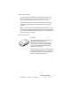
Installing the battery pack Notes: • Use only Nickel Cadmium (Ni-Cd) batteries supplied by Home Wireless Networks in the handset. For information on ordering replacement batteries, call 1-888-WHY-WIRE. Procedure 1 Remove the battery cover. 2 Connect the battery jack and insert the battery pack into place. Note: Be sure to place the end of the battery pack against (not on top of) the rubber spacer in the battery well.
Replace the battery cover. 3 Charging the Handset battery 1 Connect the handset AC Adaptor to the charging cradle and plug it into a standard 110V electrical outlet. 2 Place the handset in the charging cradle and charge the battery for 24 hours. Notes: • The battery must be installed in the handset in order to recharge it. • The handset can be placed either face up or face down in the charging cradle. The LED on the cradle illuminates when the handset is properly seated.
Registering a Handset with the Controller Before you can use a handset, it must be registered with the network controller so the two devices can communicate with each other. If you change Controllers for any reason, you must re-register the handset with the new Controller. Note: Be sure to fully charge your new handset battery before beginning the handset registration procedure. See page 32 for information on installing and charging the handset battery.
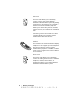
Self-registration Procedure 1 During the charging process, the handset will begin displaying the following screen. Wait until the handset has charged for a full 24 hours, then enter the last five digits of your network Controller serial number. Press END when finished. Note: See page 14 for information on locating your Controller serial number. 2 You will be asked to confirm that the entered serial number is correct. Press 1 (Yes) to confirm or 2 (No) to re-enter the Controller serial number.
Enter your Controller password, then press 0 (OK) to continue. Note: The default Controller password is “4961.” You should change this password to one of your own choosing as soon as you finish installing and setting up your network. The password can be changed via either the handset Setup menu (see “Changing the system password” on page 61), or via a PC connected to a Data Jack.
4 If the password is correct, the handset displays the following screen: Press 0 to continue. 5 The handset next displays the following screen. Enter a name that identifies the handset with a particular location or individual. Note: Handset names can be up to 10 characters in length and are entered using the handset keypad.
• • • 6 Press # to advance to the next space; Press 0 as many times as necessary to delete the remaining unwanted text. Press END when finished. When asked if the entered data is correct, press 1 for Yes or 2 for No. Note: Handset names can be changed at a later date via the Setup menu. For details, see “Changing a device name” on page 64. 7 38 • Installing Handsets When the handset displays the following screen, press 0 (OK ) to continue:.
8 When the handset displays the following screen, press 1 (YES) if you want to add another handset or a data or phone jack to the system. Proceed to Step 9 when finished. If you do not want to add another handset or a data or phone jack at this time, press 2 (NO) and proceed to Step 10.
9 If you pressed 1 (YES) in the preceding step, the following screen is displayed. Press 1 to add another handset, or 2 to add a data or phone jack. Note: If you press 1, you will be asked to enter the serial number and name of the additional device. Handset serial numbers are located on the underside of the battery cover. Data and phone jack serial numbers are located on the plug side of the jack. When you have finished adding devices to the network, proceed to the next step.
11 When the following screen is displayed, press 0 to begin using the handset. Establishing dialing rules If you have not already specified dialing rules via a PC connected to a Data Jack, you will be asked to specify them during installation of the first handset. Note: Dialing Rules tell the system how to dial local and long-distance calls (for example, when to dial “1” before an area code).
Press 2 (NO) if you do not need to dial 10 digits to reach local numbers, then proceed to Step 3. Note: 10-digit dialing is most common in rapidly growing major metropolitan areas that have more than one area code in a dialing area. Example Metro Atlanta, Georgia, is a good example of a 10-digit dialing area. Callers from within any of three Atlanta area codes can place local (non-toll) calls to any other number within those three area codes by dialing xxx-xxx-xxxx.
Follow the instructions on the display to enter all local area codes that do not require “1” before dialing. When finished, proceed to Step 6. 3 If you pressed 2 (NO) in Step 1, the following screen is displayed. Follow the instructions on the display to enter your local area code. 4 After confirming your local area code, the following screen is displayed. If you must dial “1” to reach any local prefixes, press 1 (YES) and proceed to Step 5.
Note: These are numbers that you must dial 1+xxx+xxxx (no area code) to reach. 5 If you pressed 1 (YES) in the preceding step, the following screen is displayed. Follow the instructions on the display to enter all local prefixes that you must dial “1” to reach. 6 44 • Installing Handsets When the following screen is displayed, press 0 to begin using the handset.
Installing Phone Jacks Phone Jacks allow you to connect analog devices such as standard telephones, FAX machines, modems, and answering machines to your Home Wireless Networks communication system. Registering the Phone Jack with the Controller 1 From a handset that is registered with the Controller, press MENU until you reach the screen containing the Setup function. 2 Select Setup. 3 4 5 Select Network. 6 Enter the serial number of the phone jack being added to the network.
7 When asked to enter the name of the jack, enter a name that defines the purpose of the jack. Examples: FAX, kitchen, etc. Note: Device names can be up to 10 characters in length. Example: To enter the name “FAX” • Press 3 three times to add “F”; • Press # to advance to the next space; • Press 2 two times to add “A”; • Press # to advance to the next space; • Press 9 seven times to add “X” • Press 0 as many times as necessary to delete the remaining unwanted text; • Press END when finished.
Connecting the Phone Jack 1 Plug the phone line from the fax machine, standard telephone, modem, etc. into the phone jack. 2 Connect the phone jack to the transformer. 3 Plug the transformer into a standard 110v power outlet. Note: The LED on the phone jack connector illuminates when it is receiving power and in communication with the Controller.
Handset Operation Viewing Line Status To view the status of each line, press MENU until you reach the Line Status screen. See the following example. Basic Calling Features Answering an incoming call Press TALK. Answering a specific line Select the desired ringing line number. Example: To answer a call on line 3, press 3. Making a call on the first available line 1. Press TALK or press the number associated with a particular line. 2. When you hear dial tone, dial the desired number.
Making a call on a specific line 1. Select the desired line number. Ending a call Press END. Placing a call on hold While on an active call, press HOLD. Retrieving a held call Press MENU until you reach the screen showing the held call. Call Waiting When you hear the Call Waiting tone, press FLASH to answer the waiting call. Your original call will be placed on hold. Press FLASH again to return to your original call. You can then toggle between the two calls using FLASH. 2. Dial the phone number.
Transferring a call 1. Press MENU until you reach the screen containing the Transfer function. 2. Select Transfer from the list of menu options. 3. Select the extension number you want to transfer the call to. 4. Press 0 (Okay) to transfer the call. Using the Mute function The Mute function turns the handset microphone off. You can still hear the party on the other end, but they can’t hear you. 1. While on a call, press MENU until you reach the screen containing the Mute function. 2.
Caller ID and Directory Services Features Notes: • You must subscribe to the Caller ID service provided by your phone company in order to use the following Caller ID features. • Two types of directories are available - a System Directory and a Personal Directory. The System Directory can store up to 50 entries and is available to all handsets and PCs in the network. The Personal Directory can store up 40 entries per handset (up to a maximum of 400 Personal Directory entries).
Deleting all records from the Caller ID log 1. Press MENU until you reach the screen containing the Caller ID function. 2. Select Caller ID from the list of menu options. 3. Press 9 and hold for at least 3 seconds. 4. When the confirmation screen appears, press 1 (Yes) to clear all records from the Caller ID log. Saving a Caller ID record to the Directory 1. Press MENU until you reach the screen containing the Caller ID function. 2. Select Caller ID from the list of menu options. 3.
Dialing from the Directory 1. Press MENU until you reach the screen containing the Directory function. 2. Select Directory from the list of menu options. If you have the Key System software package, you will be prompted to press 1 to reach the System Directory or 2 to reach the Personal Directory. (See note regarding Directory Services on page 51.) 3. Select the desired Directory category (2 - ABC, 3 - DEF, etc.). 4. Locate the desired Directory entry. 5. Press 5 to dial the number.
Manually adding an entry to the Directory 1. Press MENU until you reach the screen containing the Directory function. 2. Select Directory from the list of menu options. If you have the Key System Software Package, you will be prompted to press 1 for the System Directory or 2 for the Personal Directory. (See note regarding Directory Services on page 51.) 3. Press 0 to add an entry. 4. Use the keypad to enter the desired name.
Deleting an entry from the Directory 1. Press MENU until you reach the screen containing the Directory function. 2. Select Directory from the list of menu options. If you have the Key System Software Package, you will be prompted to press 1 for the System Directory or 2 for the Personal Directory. (See note regarding Directory Services on page 51.) 3. Select the desired Directory category. 4. Locate the desired Directory entry. 5. Press 9 to delete the record from the Directory.
Conference Calling Features Your Home Wireless Networks communications system allows up to 11 parties to participate in a conference call at the same time (assuming all 4 lines and the Controller E-Jack are used. Initiating a Conference Call 1. Place all parties on hold. 2. Press MENU until you reach the screen containing the Conference function. 3. Select Conference from the list of menu options. Adding another member to a Conference Call 1. Place all parties on hold. 2.
Dropping another member from a Conference Call 1. During a Conference Call, press MENU until you reach the screen containing the Conference function. 2. Select Conference from the list of menu options. 3. Press 2 to drop a member. 4. Press # to scroll through the available members. 5. When the desired member is highlighted, press 0 (OK) to drop the member from the conference.
Miscellaneous General Features Adjusting the Handset Volume 1. Press MENU until you reach the screen containing the Volume function. 2. Select Volume from the list of menu options to adjust the handset volume up and down. Adjusting the Ringer Volume 1. Press MENU until you reach the screen containing the Ringer volume. 2. Select Ringer from the list of menu options to adjust the handset volume up and down.
Locating a misplaced handset Option 1 Call the missing extension from another handset. This option causes the called handset to ring. Example: To locate extension 12, press “12.” Option 2 If you don’t know the extension number of the missing handset, you can use another handset to cause all handsets in the network to ring. 1. Press MENU until you reach the screen containing the Extensions menu item. 2. Press 7 (Extensions). 3. Scroll through the displayed items until “Ring all” is highlighted. 4.
Phone Company Calling Features If you subscribe to optional line calling services available from your phone company, the Home Wireless Networks communications system allows you to take advantage of them as described below. Note: Optional line calling features include such services as Call Waiting, Caller ID, Distinctive Ringing, Call Forwarding, etc.
Distinctive Ringing All handsets in the network will ring with the phone company distinctive ringing pattern, UNLESS you have selected a different distinctive pattern for a particular extension via the Setup menu. Voice Mail If the Voice Mail feature is activated on your system, when a voice mail message waiting signal is sent by the telephone company, all handsets in the network will display a “Message Waiting Line x” message when on the Idle screen.
System Administration via the Handset You can perform the following system administration tasks from any Handset on the network. (You will be required to first enter the system password.
Voice Mail • Turn message waiting detection on or off for each line. • Specify message detection method. Internal Modem • Specify outbound information such as location name and number, dialing schedule, and line to be used for the outdial. • Specify inbound information such as whether modem should answer incoming calls or not and specify which line the modem should answer on.
3. Enter your system password, then press END. 4. Press 1 (General). 5. Press 1 (Time/Date). 6. Enter the correct time and date as follows: Verifying the system software version • Press 1 to increment the hour • Press 2 to increment the minute • Press 3 to increment the day • Press 4 to increment the month • Press 5 to increment the date. • Press END. You can verify your system’s software version using the following procedure. Procedure 1.
individuals from registering devices on your system. The Controller comes with a default system password of “4961.” You should change this password to one of your own choosing as soon as you finished installing and setting up your network. Passwords must be a 4-digit number. Write your password down and keep it in a safe place. You will need it to perform all system administration tasks. Procedure 1. Press MENU until you reach the screen containing the Setup function. 2. Press 9 (Setup). 3.
Managing devices Adding devices to the network If you have already added a handset to the network, you can use the following procedure to add additional handsets, data jacks, or phone jacks. Note: Be sure to fully charge the battery pack before attempting to use a new handset. See page 32 for information on installing and charging handset batteries. Procedure 1. Press MENU until you reach the screen containing the Setup function. 2. Press 9 (Setup). 3. Enter your system password, then press END. 4.
10. When the display reads “Handset Added” (or “Access Jack Added”), press 0. Removing devices from the network You can remove a handset, data jack, or phone jack from the network by using the following procedure. Removing a device disables the Controller’s ability to communicate with that device. It is a generally a good security measure to remove a device that has been lost. Procedure 1. Press MENU until you reach the screen containing the Setup function. 2. Press 9 (Setup). 3.
Note: Pressing 2 will return you to the “Add, Remove, Configure” menu screen. Pressing MENU will exit the Setup function entirely. 9. When the display reads “Handset Removed” or (“Access Jack Removed”), press 0. Changing a device name You can change the name of a device using the following procedure. Procedure 1. Press MENU until you reach the screen containing the Setup function. 2. Press 9 (Setup). 3. Enter your system password, then press END. 4. Press 2 (Network). 5.
on naming handsets and data or phone jacks.) 10. Press END when finished editing the device name. Setting outbound line selection options Outbound LIne Selection options determine which lines an extension uses for outgoing calls. You can specify that a particular extension use only one line, or all lines in the network. Example: You have three handsets on Extensions 10, 11, and 12, and four phone lines. One of the handsets (Extension 11) is assigned to a warehouse worker.
6. Press 3 (Configure). 7. Enter the extension number you want to set outbound line selection for. Note: You can also use * and # to scroll through the entries. When the desired device is highlighted, press 0 (OK). 8. Press 2 (Outbound line selection). 9. Toggle the desired lines on or off by pressing the corresponding line number. A check mark indicates that the extension can use that line for outbound calls.
3. Press 1 if the extension being configured is a Handset, or 2 if the extension being configured is for a data or phone jack. 4. Press 3 (Configure). 5. Enter the extension number you want to set inbound ringing for. Note: You can also use * and # to scroll through the entries. When the desired device is highlighted, press 0 (OK). 6. Press 3 (Inbound ringing). 7. Toggle the desired lines on or off by pressing the corresponding line number.
4. Press 2 (Network). 5. Press 3 (Lines). 6. Select the desired line number. 7. Press 1 to toggle Call Forwarding on or off. 8. If you turned Call Forwarding “ON” in the preceding step, enter the number the calls should be forwarded to. Press END when finished. Setting Call Privacy for all calls on a particular line The Home Wireless Networks communications system allows you to specify that all calls on a particular line be Private.
5. Press 3 (Lines). 6. Select the desired line number. 7. Press 2 to toggle Privacy on or off. Specifying the ring pattern for a particular line You can specify a different ring pattern for all incoming calls on a specific line. This is convenient if you have a particular line dedicated for business calls, for instance, and you want to be able to distinguish incoming calls on that line from other incoming calls. Procedure 1. Press MENU until you reach the screen containing the Setup function. 2.
Specifying Tone or Pulse dialing for a particular line You can specify either tone or pulse dialing for all outgoing calls on a particular line. All calls dialed out on that line from either a handset or a device connected to a Phone Jack will use the specified dialing type. Procedure 1. Press MENU until you reach the screen containing the Setup function. 2. Press 9 (Setup). 3. Enter your system password, then press END. 4. Press 2 (Network). 5. Press 3 (Lines) 6. Select the desired line number. 7.
Use the following procedures to change dialing rules via the handset. Local area codes This section is used to define area codes that can be reached without dialing “1.” This includes your area code (xxx-xxxx), as well as any local area codes that require 10-digit dialing (xxx-xxx-xxxx). Viewing local area code settings Procedure 1. Press MENU until you reach the screen containing the Setup function. 2. Press 9 (Setup) 3. Press 2 (Network). 4. Press 4 (Dialing rules). 5. Press 1 (Local area codes). 6.
2. Press 9 (Setup) 3. Press 2 (Network). 4. Press 4 (Dialing rules). 5. Press 1 (Local area codes). If your system is set to use 10-digit dialing, the handset displays the screen shown at left. Press 0 (Okay) to display area codes where dialing 1 is not required. If your system is not set to use 10-digit dialing, the handset displays the local area code and asks if you would like to make changes. Press 1 (Yes) to make changes to the local area code. 6. Press 1 (Add). 7. Enter the new local area code.
digit dialing. If your area does not use 10-digit dialing, you must delete all area codes but one. Deleting a local area code Procedure 1. Press MENU until you reach the screen containing the Setup function. 2. Press 9 (Setup) 3. Press 2 (Network). 4. Press 4 (Dialing rules). 5. Press 1 (Local area codes). If your system is set to use 10-digit dialing, the handset displays the screen shown at left.
Within Area Rules This section is used to define prefixes within the local area code that you must dial “1” to reach (1-xxx-xxxx). Viewing settings for within area rules Procedure 1. Press MENU until you reach the screen containing the Setup function. 2. Press 9 (Setup) 3. Press 2 (Network). 4. Press 4 (Dialing rules). 5. Press 2 (Within area rules). 6. When the screen shown above is displayed, press 0 (Ok). 7. The handset displays all local prefixes where dialing 1 is required.
6. When the screen shown above is displayed, press 0 (Ok). 7. The handset displays a screen similar to the one shown at left. Press 1 (Add). 8. Enter the local prefix to be added. Press END when finished. The new prefix is added to the list. Deleting a 1+ local prefix 1. Press MENU until you reach the screen containing the Setup function. 2. Press 9 (Setup) 3. Press 2 (Network). 4. Press 4 (Dialing rules). 5. Press 2 (Within area rules). 6. When the screen above is displayed, press 0 (Ok): 7.
Behind a PBX or Key System This section is used to define local and/or long distance codes that must be dialed in order to access an outside line (common in office settings that use a PBX or Key telephone system). Viewing access code settings Procedure 1. Press MENU until you reach the screen containing the Setup function. 2. Press 9 (Setup) 3. Press 2 (Network). 4. Press 4 (Dialing rules). 5. Press 3 (Behind PBX). 6. To view the local access code setting, press 1.
6. To define the local access code setting, press 1. To define the long distance access code setting, press 2. 7. Enter the access code. 8. When asked to confirm the access code, press 1 for Yes, or 2 for No. Setting System Timers Setting the Hold Recall Timer The Hold Recall Timer determines how long a call will remain on hold before a reminder ring sounds on the extension that placed it on hold.
5. Press 5 (Timers). 6. Press 1 (Hold recall). 7. Select one of the five timer options. Setting the Transfer Recall Timer The Transfer Recall Timer determines how long a transferred call will go unanswered before it rings back to the transferring extension. When a transferred call recalls to the transferring extension, the user hears a ring tone and the handset displays “Recall Line X.
Setting voice mail options If you subscribe to your telephone company’s voice mail service, you can configure your network to display a “Message Waiting” indicator on each handset in the network. To set your network up for voice mail, you must turn message detection on for the desired lines (Line Setup), and also tell the network which detection method to use (Detection Method). Line Setup Procedure 1. Press MENU until you reach the screen containing the Setup function. 2. Press 9 (Setup). 3.
3. Enter your system password, then press END. 4. Press 3 (Voice Mail). 5. Press 2 (Message Detection). 6. If your telephone company does not use stutter dial tone to indicate a waiting voice mail message, press 1 (FSK). If your telephone company uses stutter dial tone for voice mail messages, press 2 (FSK/Stutter Tone).
3. Enter your system password, then press END. 4. Press 4 (Internal Modem). 5. Press 1 (Outbound Settings). 6. Select the location to be modified. 7. Press 1 (Edit name). Use the keypad to enter the desired name. Press END when finished.
Editing a location’s number Procedure 1. Press MENU until you reach the screen containing the Setup function. 2. Press 9 (Setup). 3. Enter your system password, then press END. 4. Press 4 (Internal Modem). 5. Press 1 (Outbound Settings). 6. Select the location to be modified. 7. Press 2 (Edit number). 8. Enter the desired number. 9. Press END when finished. Editing a location’s dialing schedule Procedure 1. Press MENU until you reach the screen containing the Setup function. 2. Press 9 (Setup). 3.
6. Select the location to be modified. 7. Press 3 (Edit schedule). 8. Specify the desired schedule: • Press 1 as many times as necessary to specify the daily frequency; • Press 2 as many times as necessary to specify the monthly frequency or day of week; • Press 3 as many times as necessary to specify the desired start time; • Press 4 as many times as necessary to specify the desired ending time. 9. Press END when finished. Specifying a line for the outdial Procedure 1.
Note: If the specified line is busy when the scheduled time arrives, the Controller will try every 30 minutes for the next 12 hours to access the line. Specifying Inbound Settings You can set your Controller’s internal modem to answer the next incoming call on a specific line. This feature is intended to allow Home Wireless Networks Tech Support to dial into your system at a pre-arranged timefor troubleshooting purposes.
Specifying the incoming line Procedure 1. Press MENU until you reach the screen containing the Setup function. 2. Press 9 (Setup). 3. Enter your system password, then press END. 4. Press 4 (Internal Modem). 5. Press 2 (Inbound Settings). 6. Press 2 (Choose Line). 7. Select the desired line. Remember that if internal modem answer is toggled ON, the next incoming call on the specified line will be answered by the Controller’s internal modem.
System Administration via your PC All system administration tasks available via a Home Wireless Networks handset can also be accomplished via a PC connected to a Data Jack. Note: You must have an Internet browser such as Netscape or MS Internet Explorer installed on your PC. Procedure 1. Launch your Internet browser. 2. Type in the following URL: ???????? 3. When the Home Wireless Networks screen appears, select “User Setup.” 4.
• Add, remove, or configure Handsets or Phone and Data Jacks (including editing names and specifying lines for inbound ringing and outbound dialing) • Set Call Forwarding, Call Privacy, Ring Pattern, or Tone/Pulse Dialing for each line • Define dialing rules - local area code(s), 10-digit dialing area codes, local and/or long distance access codes (when dialing from behind a PBX or Key system) • Set Hold Recall and Transfer Recall system timers Voice Mail • Turn message waiting detection on or off
Troubleshooting Handset displays “Controller not located” 1. You may be out of range - move closer to the Controller unit. 2. Your handset battery may be dead. Replace the battery and charge the handset for 24 hours before attempting to use it again.
The network is not operational during a power outage condition Your Controller back-up battery may be dead. Replace the battery and limit use of the network to emergencies only until power is restored. (See “Installing the battery” on page 20 for information on this procedure.) You forgot your system pasword You can reset your system to the default of “4961” by disconnecting the Controller power cord and removing the Controller battery, then reinstalling the battery and reconnecting the power.
Regulatory Information for general telephones 1. This equipment complies with Part 68 of the FCC rules. On the bottom of this equipment is a label that contains, among other information, the FCC registration number and ringer equivalence number (REN) for this equipment. If requested, this information must be provided to the telephone company. 2. The applicable registration jack (connector) USOC-RJ11C is used for this equipment. 3.
7. If trouble is experienced with this equipment, for repair or warranty information, please contact the Home Wireless Networks Customer Service Center at 1-888-WHY-WIRE. If the equipment is causing harm to the telephone network, the telephone company may request that you disconnect the equipment until the problem is resolved. 8. All repairs will be performed in an authorized Home Wireless Networks service station. This equipment cannot be used for party lines or coin lines. 9.
This equipment generates, uses, and can radiate radio frequency energy, and if not installed and used in accordance with the instructions, may cause harmful interference to radio communications. However, there is no guarantee that interference will not occur in a particular installation.
Specifications General Frequency range 902-928 MHz RF Bandwidth approx. 3 MHz 10dB BW Effective range 500 - 1000 feet Number of devices allowed on network (Handsets, Data Jacks, and/or Phone Jacks) 12 (6 can be active at any one time) Controller Size 8.5” x 4.75” x 2.25” Weight Channels 37 Bit Rate Ambient temperature range -22°F to 122°F Humidity 20% to 90% (non-condensing) Power Source 7.
Handset Size 6.75” x 2” x 1.25” Weight < 7 oz Channels 37 Voice Channel Data Rate 80 Kbits/sec Ambient temperature range -32°F to 122°F Humidity 20% to 90% (non-condensing) Power Source 3-cell AA rechargeable Ni-Cd battery pack Charging Cradle Transformer +9v/100mA Data Jack Size 4.5” x 2.75” x 1.
Phone Jack Size 4.5” x 2.75” x 1.
Warranty Information 100 • Warranty Information 35(/,0,1$5< Y
Wall Mounting Instructions Mounting the Controller on a wall Procedure Use the template on page 103 to help position the Controller on the wall. 1 Locate a wall stud in the area where you want to mount the Controller. 2 Hold the template against the wall with the crossmarks centered on the stud and mark through the center of each crossmark with a pencil or other sharppointed object. 3 Insert the mounting screws through the wallboard and into the stud at the marked locations.
Mounting the Handset charging cradle on a wall Procedure Use the template on page 104 to help position the Handset charging cradle on the wall. 102 1 Locate a wall stud in the area where you want to mount the charging cradle. 2 Hold the template against the wall with the crossmarks centered on the stud and mark through the center of each crossmark with a pencil or other sharppointed object. 3 Insert the mounting screws through the wallboard and into the stud at the marked locations.
Controller Wall Mounting Template Use this template when mounting the Controller on a wall. To mark the positions of the mounting screws, hold the template against the wall with the crossmarks centered on a wall stud. Push a pencil or pen point through the center of each crossmark to mark the wall.
Handset Charging Cradle Wall Mounting Template Use this template when mounting the Handset charging cradle on a wall. To mark the positions of the mounting screws, hold the template against the wall with the crossmarks centered on a wall stud. Push a pencil or pen point through the center of each crossmark to mark the wall.
© 1998 Home Wireless Networks, Inc. All rights reserved. 3145 Avalon Ridge Place, Suite 200 Norcross, GA, USA 30071 888-WHY-WIRE www.homewireless.