SmartVent™ BATHROOM VENTILATION FAN MODEL 7146-80-MS Español p. 13 FCC ID:SYJ7146-80-MS Questions, problems, missing parts? Before returning to the store, call our customer service department at 1-877-319-3757, 7:30 a.m. - 4:30 p.m., CST, Monday - Friday. READ AND SAVE THESE INSTRUCTIONS HomewerksWW.
TABLE OF CONTENTS Product Specifications.........................................................................................................................2 UL Compliance....................................................................................................................................2 Package Contents...............................................................................................................................3 Hardware Included........................................
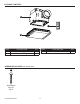
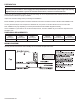
PACKAGE CONTENTS A C B PART A B DESCRIPTION Fan Housing Grille with LED Lights QTY 1 1 PART C HARDWARE INCLUDED (not actual size) AA Wood Screw M4 x 30 Qty. 8 HomewerksWW.
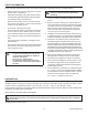
SAFETY INFORMATION Please read and understand this entire manual before attempting to assemble, operate or installthe product. • Always disconnect the power supply prior to servicing the fan, motor or junction box. • Follow all local building, safety and electrical codes as well as NEC (National Electrical Code) and OSHA (Occupational Safety and Health Act). • Electric Service supply must be 120 volts, 60 hertz. • This product must properly connect to the grounding conductor of the supply circuit.
PREPARATION efore removing your current ventilation unit, verify your switch box on the wall has the required supply wires B necessary for this installation. These supply wires are power/black and neutral/white (refer to right side of wiring diagram below) at the switch. If you do not see both of these wires, consult a licensed electrician.
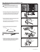
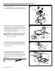
NEW CONSTRUCTION INSTALLATION INSTRUCTIONS BEFORE INSTALLATION WARNING: RISK OF ELECTRIC SHOCK. Ensure the electricity to the wires you are working on is shut off. Either remove the fuse or turn off the circuit breaker before removing the existing bath fan or installing the new one. 1. P lace the fan housing (A) next to a ceiling joist or wall stud. The fan housing (Å) should be level and perpendicular to the joist or stud. Allow for thickness of ceiling board or drywall used in your application.
NEW CONSTRUCTION INSTALLATION INSTRUCTIONS 5. R emove the wiring cover. Pull the house wires through the wiring cover hole. Using the attached quick connectors, connect 120v house wiring to the fan as shown in the wiring diagram on page 5. 12-18 AWG is the smallest conductor that should be used for branch circuit wiring. 5 Wiring cover Carefully push the connected wires back into the wiring box housing. Reattach the wiring box cover.
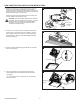
EXISTING CONSTRUCTION INSTALLATION INSTRUCTIONS BEFORE INSTALLATION WARNING: RISK OF ELECTRIC SHOCK. Ensure the electricity to the wires you are working on is shut off. Either remove the fuse or turn off the circuit breaker before removing the existing bath fan or installing the new one. 1 2. M easure the opening to ensure it is large enough to accommodate the new fan housing (A) (7-1/2 in. x 7-1/4 in.). 2 3. If this fan is not replacing an old fan, be sure to cut a 7-3/4 in. x 7-1/2 in.
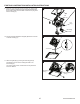
EXISTING CONSTRUCTION INSTALLATION INSTRUCTIONS 5. S lide the grille mounting brackets to the left and remove them from the fan housing (A). 5 Remove the three prong fan plug from the fan housing (A) and pull the black fan motor straight out of the metal fan housing (A). Mounting brackets Fan plug Fan motor A 6. R emove the wiring cover. Pull the house wires through the wiring cover hole.
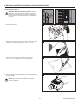
EXISTING CONSTRUCTION INSTALLATION INSTRUCTIONS 9. F it the fan motor back into the fan housing (A), aligning with the duct opening. Replace the grille mounting brackets and secure with screws removed earlier. Insert the fan plug back into the housing (A). 9 A Fan motor Fan plug Mounting brackets 10. Plug the connector attached to the grille (B) into the connector on the fan housing (A). 10 A Connector B 11.
CARE AND CLEANING CAUTION: Before attempting to clean the fixture, disconnect the power to the fixture by turning the breaker off or removing the fuse from the fuse box. • See safety information before proceeding. Routine maintenance should be done at least once a year. • Never use solvents, thinner or harsh chemicals for cleaning the fan. • Do not allow water to enter the motor.• Do not immerse metal parts in water. • Do not immerse resin parts in water more than 140°F. 1.
TROUBLESHOOTING PROBLEM POSSIBLE CAUSE SOLUTION The fan seems louder than it should. The CFM is too great. Be sure the CFM rating on the fan matches the square footage of your room. The damper is damaged or not working properly. Check the damper to ensure it is opening and closing properly. If the damper has become damaged, please call Customer Service. The bend in the duct is too close to the fan discharge. Be sure you do not have any sharp bends in the duct within 18 in. of the fan discharge.