Item #1008 601 325 1008 601 322 1008 601 321 Model # N381B-BN N381B-CB+MBK N381B-MBK 1008 601 324 1008 601 323 N381B-MBK+V8 N381B-MWH USE AND CARE GUIDE 60 IN EASTON INDOOR/COVERED OUTDOOR CEILING FAN Questions, problems, missing parts? Before returning to the store, call Home Decorators Collection Customer Service 8 a.m. - 7 p.m., EST, Monday - Friday, 9 a.m.- 6 p.m., EST, Saturday 1-800-986-3460 HOMEDEPOT.COM/HOMEDECORATORS Visual instruction of how to install this fan: Visit www.homedepot.
Table of Contents Table of Contents . . . . . . . . . . . . . . . . . . . . . . . . . . . . . . . . . . 2 Safety Information . . . . . . . . . . . . . . . . . . . . . . . . . . . . . . . . . 2 Warranty . . . . . . . . . . . . . . . . . . . . . . . . . . . . . . . . . . . . . . . . . 3 Pre-installation . . . . . . . . . . . . . . . . . . . . . . . . . . . . . . . . . . . . 3 Installation . . . . . . . . . . . . . . . . . . . . . . . . . . . . . . . . . . . . . . . 6 Assembly . . . . . . . . . . . . . . . .
Warranty The manufacturer warrants the fan motor to be free from defects in workmanship and material present at time of shipment from the factory for a period of lifetime after the date of purchase by the original purchaser. The manufacturer warrants the light kit (excluding any glass), to be free from defects in workmanship and material present at time of shipment from the factory for a period of five years after the date of purchase by the original purchaser.
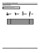
Pre-Installation (continued) HARDWARE INCLUDED NOTE: Hardware not shown to actual size. AA Part BB DD CC Description Quantity AA Plastic wire nut 3 BB Blade attachment screw and lock washer (additional) 1 CC 1.
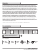
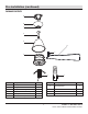
Pre-Installation (continued) PACKAGE CONTENTS A B C D E H G F 6 1 2 3 5 4 1H 3H 6H I Part Description Quantity A Mounting bracket 1 B Canopy 1 J Part Description Quantity G Blade support plate with screws and lock washers 3 C Canopy bottom cover (preassembled) 1 H Blade 3 D Hanger ball/downrod assembly 1 I Receiver 1 E Coupling cover 1 J Remote control 1 F Fan motor assembly 1 5 HOMEDEPOT.
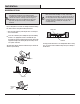
Installation MOUNTING OPTIONS NOTE: You may need a longer downrod to maintain proper blade clearance when installing on a steep, sloped ceiling. The maximum angle allowable is 18° away from horizontal. If the canopy (B) touches the hanger ball/downrod assembly (D), remove the decorative canopy bottom cover (C) and turn the canopy (B) 180° before attaching the canopy (B) to the mounting bracket (A).
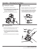
Assembly — Attaching the Fan Blades 1 2 Preparing the canopy Attaching the fan blades Remove the canopy bottom cover (C) from the canopy (B) by turning the canopy bottom cover (C) counterclockwise. Align the blade notches with the motor posts. Attach the blade (H) to the fan motor assembly (F). Align the holes on the blade support plate (G), the blade (H), and the fan motor assembly (F) and secure with the blade attachment screws and lock washers.
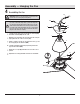
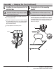
Assembly — Hanging the Fan 4 Assembling the fan DD WARNING: Failure to properly install the cotter pin (FF) could result in the fan loosening and possibly falling. KK NOTE: If a longer downrod (not included) is needed, take out the screw located in the hanger ball (JJ), lower the hanger ball (JJ) and remove the pin (KK). Remove all three pieces from the downrod and assemble them onto the new longer downrod before proceeding to the downrod installation.
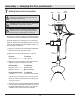
Assembly — Hanging the Fan (continued) 5 6 Installing the mounting bracket to the electrical box Hanging the fan to the mounting bracket WARNING: The tab in the ring must rest in the groove of the hanger ball/downrod assembly (D). Failure to properly seat the tab in the groove could cause damage to the wiring.
Assembly — Hanging the Fan (continued) 7 Making the electrical connections Black White Ground conductor WARNING: Check to see that all connections are tight, including ground, and that no bare wire is visible at the wire nuts (except for the ground wire). Outlet Box CAUTION: To reduce the risk of electric shock, this fan must be installed with an isolating wall control/switch. A NOTE: The fan must be installed at a maximum distance of 20 ft.
Assembly — Hanging the Fan (continued) 8 Finishing the fan installation WARNING: Make sure the tab on the mounting bracket properly sits in the groove in the hanger ball before attaching the canopy to the bracket by turning the housing until it drops into place. Outlet Box A EE NN NOTE: Adjust the canopy mounting screws as necessary until the canopy and canopy bottom cover are snug. EE Make sure connections are neatly tucked into the ceiling outlet box.
Operation SETTING UP THE TRANSMITTER NOTE: The remote has been pre-paired in the factory for your convenience. J NOTE: Batteries will weaken with age and should be replaced before leaking takes place as this will damage the remote control. Dispose of used batteries properly and keep them out of the reach of children. Remove the battery cover by pressing firmly on the arrow and sliding the cover off. CC Install two 1.5V AAA batteries (CC) (included). Replace the battery cover on the remote control (J).
Operation (continued) Signal light 6 Power on/off 1 2 Fan speed 3 5 4 Comfort BreezeTM Fan reverse 1H 3H 6H Timer OPERATING YOUR FAN AND REMOTE CONTROL NOTE: The fan will store the last used speed setting for the next time it is turned on. NOTE: You must turn the fan on prior to using the speed or time functions. NOTE: On each start up of your ceiling fan, the fan blades will oscillate back and forth. This is a NORMAL OPERATION for DC motor ceiling fans as they go through a calibration cycle.
Operation (continued) Comfort BreezeTM Pressing the button will activate the Comfort BreezeTM mode. If you are using Comfort BreezeTM mode, pressing the the fan speed buttons will cancel Comfort BreezeTM mode and resume normal fan operation. Fan reverse button (Must be pushed when the fan is in operation) Controls fan direction. Timer 1H 3H 6H Pressing the timer button will automatically turn fan and light (if light is on) off after 1, 3, or 6 hours.
Operation (continued) INSTALLING THE REMOTE CONTROL HOLDER QQ Attach the remote control holder (PP) with the two remote control holder mounting screws (QQ). PP WARM/COOL WEATHER OPERATING INSTRUCTIONS Speed settings for warm or cool weather depend on factors such as the room size, ceiling height, numbers of fans. NOTE: The fan reverse buttons must be pressed while the fan is running. Warm weather - (Counterclockwise Direction) A downward air flow creates a cooling effect.
Care and Cleaning Do Check the support connections, brackets, and blade attachments twice a year. Make sure they are secure. Because of the fan’s natural movement, some connections may become loose over time. It is not necessary to remove the fan from the ceiling. Clean your fan periodically. Use only a soft brush or lint-free cloth to avoid scratching the finish. The plating is sealed with a lacquer to minimize discoloration or tarnishing.
This device complies with part 15 of the FCC Rules. Operation is subject to the following two conditions: (1) This device may not cause harmful interference, and (2) this device must accept any interference received, including interference that may cause undesired operation. WARNING: Changes or modifications to this unit not expressly approved by the party responsible for compliance could void the user's authority to operate the equipment.