Owner's Manual Includes the SIA CP-01 Control Panel Standard Features for False Alarm Reduction Document Number 21R00-1 Rev. 2.
Document Number 21R00-1 Rev. 2.13 September, 2006 Copyright © 2000-2006 HAI All Rights Reserved www.homeauto.
Contents INTRODUCTION........................................................................................................................................... 1 Underwriter's Laboratories (UL) Listing .........................................................................................................................................1 OVERALL DESCRIPTION .......................................................................................................................... 2 Console Operation ......
CONTROL .................................................................................................................................................... 15 About UPB.....................................................................................................................................................................................15 HAI Lighting Control (HLC) Format..............................................................................................................................
Status..............................................................................................................................................................................................33 Configuring HLC Devices ........................................................................................................................................................34 Configuring HLC Devices using an Omni Console.........................................................................................
Alarm Event Buttons.................................................................................................................................................................54 X-10 Event Buttons...................................................................................................................................................................54 Miscellaneous Event Buttons......................................................................................................................
UNDERWRITER'S LABORATORIES REQUIREMENTS ................................................................... 71 FEDERAL COMMUNICATION COMMISSION NOTICE: ................................................................. 72 CANADIAN INDUSTRY CANADA NOTICE.......................................................................................... 73 APPENDIX A - SPECIFICATIONS...........................................................................................................
INTRODUCTION Thank you for purchasing your new OmniLT automation system. You are about to experience a new feeling of comfort, convenience, and control. Please take a few moments to become familiar with all of the features of this fine product by reviewing this manual. Please keep this manual on file for future reference. It is recommended that you also review the installation and operating instructions provided with your smoke and gas detectors (if used in your system).
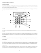
OVERALL DESCRIPTION Console Operation The console is designed with everything that is necessary for you to program and operate your OmniLT control and security system. Because we feel that it is very important for you to feel comfortable with the operation of your OmniLT, we recommend that you start by becoming familiar with your console. The OFF (1), DAY (2), NIGHT (3), and AWAY (4) keys are called shortcut keys.
6- UP ARROW The Up Arrow key is used to scroll through menus and lists. The Up Arrow is used to scroll back through a list (for example, if you have already used the down arrow to scroll to an item, the Up Arrow will bring you back to a previous item). 7- CONSOLE LED The Console LED is used to indicate whether the security system is currently armed or disarmed. If armed in any of the security modes, the LED will be set to red. If the system is disarmed, the LED will be set to green.
When using the arrow keys to scroll through lists of units, zones, buttons, codes, and temperature zones, only the named items are displayed. If no text description has been given to an item, it will be skipped over when scrolling through that list. You can still enter any item number to access it directly, and then scroll up and down among the named items. To look at another specific item, simply enter the item number followed by the Down Arrow key.
Confirmation Beep When you have successfully completed a function, such as entering a program or changing a setup item, the console will beep once. Cancel If you are ever unsure and wish to return to the top-level display, press the ' * ' key. You may have to press it more than once, depending on how far into the function (menu) you are. Each time you cancel out of an operation, the console will beep once to indicate that you have canceled.
SECURITY SYSTEM OPERATION Disarming the Security System and Silencing Alarms Before going any further, you should know how to disarm your security system in the event that the alarm sounds. Turning the system OFF disarms the burglar alarm, resets emergency alarms, and silences all sirens and sounders. Press the OFF key. OFF Watch the display. The top line will read "DISARM" - The bottom line will read "ENTER CODE", indicating that you must enter your code number to disarm the system.
2 = NIGHT The NIGHT mode is used when you are asleep and everyone in your household is at home. In the Night mode, your doors, windows, and non-sleeping area (i.e. downstairs) motion detectors are armed. In the Night mode, there is no entry delay. The alarm system sounder will be activated immediately if any door, window, or non-sleeping area (motion detector) is tripped. 3 = AWAY Use the AWAY mode when you leave your house and no one is home. All doors, windows, and motion detectors are armed.
What Happens When You Arm the Security System To arm the system into one of the 6 security modes, from the security menu, choose the security mode and press the appropriate key (1 - 6), and then enter your user code number on the console keypad or use one of the Shortcut Keys as described. ¾ The console will beep once and the console LED will be set to red ¾ The controller will cycle power to reset smoke detectors ¾ The top line will display the security mode.
Bypassing Zones 8 = BYPASS You can Bypass a zone that you do not want protected while the system is armed. Bypassing is also the only way that a tamper or panic zone can be disarmed. For example, if there is a liquor closet or gun case on a tamper zone, then you must bypass that zone to gain access to it. Another reason to Bypass a zone is if the zone is having trouble. If a zone is causing a trouble indication, you can bypass that zone to "cut it out" of the system until repairs are made.
What To Do When You Come Home If you enter your home while the system is armed in the Day, Night Delay, Away, or Vacation mode using an entry door: • The console beeper comes on and beeps 4 times per second. • The console display indicates: " *** DISARM SYSTEM *** - PRESS OFF THEN CODE" • Any lights or control modules programmed to come on for the door that you used will do so. • The system will wait the Entry Delay time. You should go to your console and immediately disarm the security system.
Fire Alarm Activated When the fire alarm is activated by the smoke/fire detector(s), the alarm responds exactly as described under Burglar Alarm Activated, except: • The console display reads, "FIRE ALARM! ZONE NAME TRIPPED". • The sounder will activate in a 3 pulse temporal pattern to distinguish the fire alarm from the burglar alarm. The fire alarm takes priority over the burglar alarm, however, if a gas alarm is already active, it will not override the gas alarm.
Police Emergency When the 1 key and the 3 key is pressed simultaneously, the Police Emergency alarm is activated. This alarm operates exactly the same as described for Burglar Alarm Activated except: • The console display indicates: "BURGLARY! - POLICE EMERG TRIPPED". Fire Emergency When the 4 key and the 6 key is pressed simultaneously, the Fire Emergency alarm is activated.
Trouble Indications The OmniLT constantly monitors the alarm zones and several internal matters and will alert you if it detects trouble. The particular trouble is indicated on the bottom line of the display and a trouble signal is given by beeping the console beeper continuously, 2 beeps per second. When any trouble condition occurs, the console will beep twice per second and continue to beep until the ' * ' key (cancel) is pressed to acknowledge the trouble.
Manager Code The Manager codes can arm/disarm the security system during assigned times. The Manager code can access functions that are code protected in High Security mode. Managers may also access the system from an outside telephone line. User Code User codes can only be used to arm and disarm the security system during assigned times. Duress Code If you are forced to disarm the system against your will by an intruder, disarm it as you normally would, but use the Duress Code instead of your normal code.
CONTROL The control features of the OmniLT make it easy and convenient to control almost any light or appliance from the console or over the telephone. You may also have your heating and air conditioning (HVAC) under control of the system, which will allow you to save energy dollars by setting the temperature appropriately when you are home, asleep, or away. Furthermore, the OmniLT can be used to program lights to make your home look occupied as a deterrent to potential thieves.
When set to UPB, the OmniLT controller can: ¾ ¾ ¾ ¾ ¾ ¾ ¾ ¾ Send commands (on, off, bright, dim and level) to individual switches and modules Receive commands and status from individual switches and modules Send commands to keypad controllers to change scenes and control LED backlight behind the keys Receive commands when buttons are pressed on keypad controllers to activate controller macros Send Link commands to switches, modules, and keypad controllers to activate scenes Receive Link commands when a but
When “Status Tracking” is enabled (this is the default setting), OmniLT keeps track of the exact status of each unit even when a lighting scene is initiated by the Room Controller. Room Controllers also keep track of when individual switches in a room are turned on and off. When all of the lighting loads in a room are turned off, the “Off” indicator is illuminated.
When set to RadioRA, the OmniLT controller can: ¾ ¾ ¾ ¾ Send commands (on, off, and level) to individual Switches and Dimmers Receive status (on and off) from individual Switches and Dimmers Receive commands when buttons are pressed on Master Controls Execute Phantom Button commands About ALC ALC is intended for installation in homes, which have been pre-wired for installation of ALC system products.
Scrolling Through Names The OmniLT stores names for Units, Zones, Buttons, Codes, Temperatures, and Messages so that you don't have to remember that "UNIT 5" is the "DEN LIGHT" and "ZONE 1" is the "FRONT DOOR". In general, any time you enter a unit, zone, button, code, temperature, or message number, you can press the down arrow key to display its name, then use the up and down arrow keys to scroll through the list of other names. This is true when entering commands and programming on the console.
Each lighting scene can also be set or easily changed using the pushbuttons on the HAI UPB™ 6-Button Room Controller, as follows: Step 1 2 3 4 Operation Press the desired pushbutton on the HAI UPB™ 6-Button Room Controller to activate the current scene (preset lighting level) in each of the HLC devices. Use the local Decora-style rocker switch on each UPB™ Wall Switch Dimmer(s) to set the desired lighting level(s) or issue commands from the OmniLT controller.
¾ 5 (RMP) does not affect CentraLite units. ¾ Press 9 (TIM) to time the selected unit (On or Off). Timed commands may be from 1-99 seconds, 1-99 minutes or 1-18 hours. ¾ Press # (STA) to see the status (On or Off) of a CentraLite device. Controlling RadioRA Units Entry Lights 0=OFF 1=ON 2=DIM 3=BRT ↓ Entry Lights 4=LVL 5=RMP 9=TIM #=STA↑ ¾ Press 0 (OFF) to turn the selected unit off ¾ Press 1 (ON) to turn the selected unit on. ¾ 2 (DIM) does not affect RadioRA units.
Ramp Command (ALC) When ALC Switch Modules are being used, it is possible to ramp the lighting level of an ALC Dimmer Switch to a new level at a selectable ramp rate. Only ALC Dimmer Switches respond to the Ramp command. Press the 5 (RAMP) key to select the ramp command. The keypad will then prompt you for the desired ramp rate: ENTER RATE: MINUTES (1-99) #=H/M/S The rate specifies the time it takes the switch to go from full off to full on, or from full on to full off.
Timed Commands The timed commands allow a units to be turned on or off for a specified period of time. The unit may be turned On for 1-99 (minutes or seconds), or 1-18 hours, then Off; or turned Off for 1-99 (minutes or seconds) or 1-18 hours, then On. Lighting units (1-16) may also be dimmed or brightened for a specified period of time.
Controlling Outputs The OmniLT has 2 (expandable to 10) outputs that can be used to switch relays. Outputs 1 and 2 are controlled by unit numbers 27 and 28. These are hardwired outputs that are connected directly through the OmniLT and not through a module. If you have something connected to these outputs, such as a sprinkler system, your dealer will explain its operation. • • Outputs cannot be brightened or dimmed. Outputs are not affected by All ON or All Off commands.
Leviton Scene Control OmniLT supports Leviton Scene Control (a feature found in certain Leviton Switches. There are 16 Scenes that can be set and executed. The Leviton Switches are divided into "lighting groups" of four units each. Each of these lighting groups can be set to four different Scenes. Once the Scenes have been set up, a command can be sent to the units in that Scene to simultaneously return to the preprogrammed lighting level.
Scene Off Command Once the Scenes have been sent, press the 0 (OFF) key to command the four units in that Scene to turn off. Notes: 1. When sending Scene Commands, the controller must be configured to allow Extended Code transmissions. 2. The Scene Commands always apply to a group of four consecutive units, which are units 1-4, 5-8, 9-12, and 13-16. You must address the units accordingly so that the desired units fall into the appropriate lighting groups. 3.
Executing Phantom Buttons OmniLT can turn on and turn off each of the 17 possible Phantom Buttons. Phantom Buttons must be pre-programmed into the RS-232 interface or Chronos. Phantom Button 16 is always assigned to “All On” (if the Phantom button is turned on or off) and Phantom Button 17 is always assigned to “All Off” (if the Phantom button is turned on or off).
Dinner for Two (Button 3): dim the dining and living room lights turn on the porch light turn off all the bedroom lights dim the den light turn on the stereo To activate a preprogrammed button, from the top-level display or from the main menu, press the 3 (BTTN) key on the console keypad. Select the button (macro) to be activated by using the arrow keys to scroll through a list of buttons, followed by ' # '.
After the ' # ' key is pressed, a menu appropriate for the type of temperature zone is shown. For Celsius temperatures, press the ' # ' key prior to entering the temperature to make the number negative. The Celsius temperature may also be specified in 0.5 degree steps, if three numeric digits are entered. The third digit adds a .5 to the first two digits, if it is anything other than zero. Enter a leading zero, if necessary.
For a heat/cool thermostat, the status shows the current temperature, the heating and cooling temperature setpoints, whether hold mode is on, the system mode, and the fan On/Auto selection. Upstairs HEAT: 70 TEMP: 78 COOL: 78 Upstairs MODE: AUTO FAN: AUTO ↑ ↓ If hold mode is On, "HOLD" is shown: Upstairs MODE: AUTO HOLD FAN: AUTO ↑ For a heat or cool thermostat, the status shows the current temperature, the temperature setpoint, whether hold mode is on, the system mode, and the fan on/auto selection.
To set up your thermostat for use with the energy saver, set it in the appropriate mode and set the temperature to your preference. NOTE: Your heating and cooling system will always be off if you set your thermostat to Off mode. The PESM cannot turn it back on. The PESM cannot make your system cool below the thermostat's cool setting, or heat above the thermostat's heat setting.
IMPORTANT NOTES: ¾ There is a 3-minute minimum on and off time for PESMs designed to prevent short cycling your HVAC compressor. If the PESM has just turned the HVAC system on or off, it will wait 3 minutes before changing it, even though the display does change.
Temperature Control of Appliances You can control appliances connected to X-10 and ALC modules (such as a ceiling fan) using the Button feature of the OmniLT. For example, the ceiling fan can be programmed to come on if the temperature goes above the High temperature (a programming example to set this up is shown in the Programming section). High and Low setpoints for temperature zones are changed the same way as the PESM. However, on/off control of the ceiling fan is done from the 1 (CONTROL) menu.
You may enter a unit number to start displaying the status of that unit, or simply press the down arrow key to scroll through the list of units. The status display is as shown under Control, except that now the arrow keys may be used to continue scrolling between units. Porch Light LAST COMMANDED 00:24:19 ON ↓ You can also check the state and (if any) the remaining time duration of any Unit.
Configuring HLC Devices using an OmniTouch Touchscreen To configure HLC devices from an OmniTouch touchscreen, press the “Control” icon on the Home page. Select the desired unit from the Control list box to display the unit dialog. Put the selected HLC device into Setup Mode (See - Setup Mode for HLC Devices), and then press the “Config” button. The display will provide you with step-by-step configuration status. Once completed, press the Exit icon.
3 = SUN (SUNRISE / SUNSET AUTOMATIC CALCULATION) The system automatically calculates the time of sunrise and sunset each day.
5 = TEMP (TEMPERATURE) The Temperature Status menu allows you to view and scroll through the status of each Thermostat, PESM, and Temperature Sensor. To enter the Temperature menu, from the Status menu, press the 5 key on the console keypad. The system will display: TSTAT 1 HEAT:60 TEMP:80 COOL:82 ↓ You may enter a unit number to start displaying the status with that unit, or simply press the down arrow key to scroll through the list of temperature zones.
For trouble restorations, the event log will show the zone name or specific trouble condition and "TRBL RST": 11:57 AM BATTERY 5/8 TRBL RST The system records each remote access. A remote phone access is when someone calls into the system from an outside phone line. Remote phone access is also recorded if the system phones out in response to an alarm and the called party enters a code.
Clear Message The 3 (CLEAR) key allows you to clear the selected text message, or all text messages from the console's display. TRASH NIGHT ENTER MESSAGE 0=ALL ↓ You may enter the message number followed by the ' # ' key to clear that message, or simply press the down arrow key to scroll through a list of messages. Press the ' # ' key to clear the selected message, or press 0, then ' # ' to clear all messages.
Pro-Link also has the capability to monitor the serial port for incoming text messages. When a text message is received, Pro-Link searches through all 16 messages for a matching message. If one is found, the Program Command (macro) corresponding to the matching message is activated. When receiving an ASCII message that is over 15 characters, OmniLT only processes the last 15 characters of the message.
TELEPHONE CONTROL Telephone Interface Your OmniLT is equipped with a built-in telephone response feature that allows you to control and access the status of your system from any Touch-Tone phone. The OmniLT actually talks to you using a digital recording of an actual human voice, so the sound is incredibly life like. You send commands to the OmniLT using the keys of your Touch-Tone telephone.
Phone Access Denied - Remote Lockout The OmniLT has a remote lockout feature to discourage youngsters (and adults who act that way) from trying to access your system. If four invalid codes are entered, the system will hang up and a one-hour lockout period will begin. During the lockout period, the OmniLT will not answer a call after any number of rings, which should discourage the caller.
When you are finished with the voice menu, press the 9 (Good-Bye) key. The OmniLT will say, "GOOD-BYE" and hang up. From an in-house phone, the dial tone will return. From a remote phone, you will hear a click as the OmniLT hangs up. It is recommended that you press 9 to terminate a remote call. If you don't, the OmniLT will hang up anyway after about 15 seconds. Recording Your Address The "Phone" menu allows you to record and verify your address. The address is used only for the VOICE dial out feature.
Emergency Dial-Out Emergency dial out consists of two distinct parts: the "digital dialer" and the "voice dialer". Digital Dialer The digital dialer (also called a "digital communicator") reports alarm events to a central station monitoring center. The digital dialer sends a digitally coded message to the central station's receiver and computer. The computer in the central station presents your name, address, and other information to a human operator who notifies the appropriate authorities.
What You Hear - If Your OmniLT Calls You When you pick up the phone and say something, the OmniLT will say: (One of the following, depending on type of alarm) - BURGLAR ALARM FIRE ALARM AUXILIARY ALARM TEMPERATURE ALARM WATER ALARM GAS ALARM SILENT ALARM AND - ADDRESS: (Your address here) PHONE NUMBER (your phone number here) The OmniLT will repeat this message twice.
SETUP The Setup menu is used to configure operating parameters, program your system to do its automated control and security functions, and give descriptions (names) for all of your zones, units, buttons, codes, temperatures, and messages. To enter the Setup menu, from the top-level display or from the main menu, press the 9 (SETUP) key on the console keypad.
You can specify the access (on/off) times for the code, this is, the time periods during which the code is valid. CODE X ON TIME: 8:00 AM MTWTF-- #=CHNG CODE X OFF TIME 5:00 PM MTWTF-- #=CHNG The times and days are changed by pressing the ' # ' KEY. Choose the 1 (TIME) key to change the On or Off times. You will be prompted to enter the new time. AM/PM must be specified for the time if the AM/PM format is being used, otherwise the entered time should be 13:00-23:59. Each item defaults to its current value.
Finally, you are prompted to enter the current date: ENTER DATE: MMDDYY Enter the current date. If the current date is February 8, 2006, enter it as “0 2 0 8 0 6”. Advanced Control Programming (ACP) Your OmniLT can be programmed to do automated control and security functions on a time schedule or in response to an event occurring in the system.
Selecting the 1 (CTRL) or 5 (TEMP) key will prompt you to specify the desired unit or temperature zone. These can be specified by entering the number, followed by the ' # ' key or by using the arrow keys to scroll through a list of items. UNIT: ENTER UNIT ↓ TEMPERATURE ZONE ENTER TEMPERATURE ZONE ↓ Selecting the 3 (BTTN) key will prompt you to specify the desired button number.
3 = Delete All Programs To delete All automation programs, from the Set Up Program menu, press the 3 (DELETE) key. The display will prompt you to confirm the deletion. DELETE ALL PROGRAMS? 0=NO 1=YES Select 1 (YES) to delete all automation control programs in the system. Select 0 (NO) or press the ' * ' key to return to the Set Up Program menu. NOTE: IF YOU CHOOSE THIS OPTION, ALL OF YOUR PROGRAMS WILL BE LOST PERMANENTLY. Edit Programs The Edit Program menu is used to create an automation program.
You may also choose to have the program execute up to 120 minutes before or after the time of sunrise or sunset. SUNSET 1=BEFORE 2=AFTER #=AT If the 1(BEFORE) or 2(AFTER) key is selected, you will be prompted to select the amount of minutes: ENTER OFFSET: 0-120 MINUTES When entering a time of day, AM/PM must be specified for the time if the AM/PM format is being used. Otherwise the entered time should be 13:00-23:59.
Control Unit / Switch Press Event Buttons This Event Button is activated upon the following: • • • • • When the specified Unit is turned on or off When the top-rocker or bottom-rocker is pressed on a UPB, RadioRA, or ALC switch When a button is pressed on a UPB 6-Button or 8-Button Keypad When a button is pressed on a RadioRA Master Control When a button is pressed on a ALC 4-Button Scene Switch Module Press the 1 (CTRL) key to select the "When Command" for a control unit event.
After the security mode is selected, an additional menu appears which allows you to further specify the button. For example, you would like to activate a button when you arm the system into the 3 (AWAY) mode: WHEN AWAY: 1=DELAY 2=CODE Any of these may be selected alone or in combination. As each item is specified, the menu is redisplayed with the updated event button description. Press the ' # ' key when done.
If Leviton Scene is selected, you must first specify the scene number: ENTER SCENE: 1-64 Then select the specified command Off, On, or Set. If UPB Link is selected, you must first specify the link number: ENTER LINK: 1-250 Then select the specified command Off, On, or Set.
You are then prompted to enter the X-10 unit code: X-10 UNIT CODE: 1-16 0=ALL Finally, you are prompted to specify the command that activates the event button: WHEN X-10 A1: 0=OFF 1=ON 2=SCENE After specifying the X-10 House Code and X-10 Unit Code, select 0 for Off, 1 for On, or 2 for Scene. "Off" events will be activated whenever the selected device is turned off. "On" events will be activated whenever the selected device is turned on.
Pro-Link determines that a message has been received when: • • • One or more characters have been received followed by 100 ms of silence One or more characters followed by a carriage return character are received One or more characters followed by a line feed character are received It is not necessary to enter the terminating carriage return or line feed character as part of the message name.
On the 6-Button Keypad: LED 1 is behind the “On” button, LED 2 is behind the “Off” button, and LED 3-6 is behind the A-D buttons, respectively. On the 8-button Keypad: LED 1-8 is behind the 1-8 buttons, respectively. For example: WHEN U1 SW 3: UNIT 1 LED 3 ON This program illuminates the “A” button (on a 6-Button Keypad) when the “A” button on that keypad controller is pressed. This program can also be used to illuminate the “3” button (on an 8-Button Keypad) when the “3” button is pressed.
Program All On / All Off Commands Select the 4 (ALL) key to program All Lights On and All Units Off commands. It is also used to program Leviton Scenes, UPB Link, RadioRA Phantom Button, or CentraLite Scene. ALL 0=OFF 1=ON 2=SCN 3=LINK↓ ALL 4=PHANTOM 5=CENLIT ↑ Program Video Commands* This program command is used to display video automatically on an OmniTouch with Video touchscreen when an event occurs.
Program Control Conditions Press the 1 (CTRL) key to specify that the program should only execute if a specified control unit is either On or Off. The display prompts for the unit number: UNIT: ENTER UNIT ↓ Enter the unit number followed by the ' # ' key, or use the arrow keys to select the unit.
Program Other Conditions Select the # (OTHER) key to select a condition from a list of other conditions. SELECT CONDITION: NONE ↓ Choose "NONE" when editing a program and choose not to conditionalize the program. SELECT CONDITION: NEVER Choose "NEVER" if you wish to temporarily deactivate a program without deleting it.
Remote Commands The Remote Commands Ok item allows you to prevent any commands from being issued from a remote telephone. If Remote Commands Ok is set to Yes, the OmniLT will allow all commands to be executed when called from a remote telephone. If Remote Commands Ok is set to No, then lights, appliances, and the security system cannot be controlled from a remote telephone that dials into your home. You can issue commands from a local (in-house) phone with Remote Commands Ok set to Yes or No.
Dial out number 1 has two times associated with it, an On and Off time. The OmniLT will only call this number if the time and days are between the Dial Out 1 On and Dial Out 1 Off times and dates. Press # to change the On and Off times - See Set Up Codes. DIAL OUT 1 ON: 12:00 AM MTWTFSS #=CHNG DIAL OUT 1 OFF: NEVER #=CHNG For example, if your normal work hours are 8 to 5 Monday through Friday, then set Dial Out 1 On to 8:00 AM MTWTF and Dial Out 1 OFF to 5:00 PM MTWTF.
Exit Delay The Exit Delay is the time, in seconds, that you have to leave your house when you turn on the system. When arming the system in Day, Night, Away, or Vacation modes, the system will wait this amount of time before arming. EXIT DELAY: 45-180 SECONDS 60 The default Exit Delay is 60 seconds. You may change it from 45 to 180 seconds. Exit Time Restart When Exit Time Restart is set to Yes, the Exit Delay will restart if the same exit zone is violated twice within the original exit delay.
Enable Auto Bypass With Auto-Bypass set to “No”, all zones to be armed must be secure when the system is armed. Otherwise, the console will beep three times and display "ZONE NOT RDY". If the system is armed and a zone is open when the Exit Delay expires, the alarm will sound. The default for Enable Auto Bypass is No. All On For Alarm This option will instruct OmniLT to execute an X-10 All On command in the event that any type of alarm occurs.
Flash For Alarm You may enter one unit number that will flash On and Off continuously when the alarm is activated. This should be an outside light to alert neighbors and police to your property if the alarm is activated. The default Flash For Alarm is Unit 2. You may enter one number for the unit number you wish to have flash, or ' 0 ' for none. Console 1-4 Audible Exit Delay Consoles (and touchscreens) 1-4 can be configured to beep while the exit delay is in effect.
Notes: 1. When configured, the House Code will affect 2 rooms of HLC lighting (i.e. HC 1 ALL OFF affects Room 1 and 2). 2. When the House Code is configured as UPB, RadioRA, or CentraLite, “House Code All Off” does not affect the state of the installed devices; however, if this setup item is set to “Yes”, OmniLT will change the status of all units on that House Code to “Off” (even though it doesn’t explicitly send an All Off command to those units).
Latitude, Longitude, and Time Zone The system automatically calculates the time of sunrise and sunset each day. Sunrise/sunset can be specified as the time a scheduling command is executed, as an enable/disable time, or as a darkness condition on a scheduling command or event button. To enable the system to properly calculate sunrise and sunset times, you must enter your latitude, location north or south of the equator, longitude, location east or west of the Prime Meridian, and time zone.
Daylight Savings OmniLT automatically calculates the day of daylight savings time each year. It also adjusts the "time of day" each time daylight savings time begins and ends. To enable the system to properly calculate daylight savings time, a start month, start weekend, end month, and end weekend is set-up at the factory. You may change or disable this function if desired.
Set Up Names The system can be set up to display descriptive names such as "FRONT DOOR", "JOHN'S BEDROOM", or "PORCH LIGHT" for zones, units, buttons, codes, temperatures, and messages. These names are displayed instead of the zone, unit, button, code, temperature, or message number that is normally displayed. Zone and Message names may be up to 15 characters long. Each of the other names may be up to 12 characters long. To enter the Set Up Names menu, from the Setup menu, press the 7 (NAME) key.
Set Up Address The final setup item is accomplished over the telephone. This is the address that the system says when it dials out in an emergency. Your voice will be recorded on computer chips in the OmniLT controller and saved to be played back in the emergency message when the system dials out for an alarm. Pick up an inside phone and press the ' # ' key on the telephone within 3 seconds of picking up the phone. The OmniLT will respond with a menu. Press 8 on the telephone keypad, then 8.
UNDERWRITER'S LABORATORIES REQUIREMENTS For a complete list of requirements and restrictions when installing the OmniLT panel in a UL Listed system, refer to the Underwriter's Laboratories Requirements section of the Installation Manual (21I00-1). When used in UL Listed Installations, the following items apply: 1. 2. 3. 4. 5. 6. The “High Security Mode” must be ON. The “Enable Auto Bypass” feature must be OFF.
FEDERAL COMMUNICATION COMMISSION NOTICE: 1. This equipment complies with Part 68 of FCC Rules. On the door, inside of the OmniLT enclosure, is a label that contains, among other information, the FCC registration number and Ringer Equivalence Number (REN) for this equipment. If requested, provide this information to your telephone company. 2. An FCC compliant telephone cord and modular plug is provided with this equipment.
CANADIAN INDUSTRY CANADA NOTICE Notice: The Industry Canada label identifies certified equipment. This certification means that the equipment meets certain telecommunications network protective, operational and safety requirements. The Industry Canada does not guarantee the equipment will operate to the user's satisfaction. Before installing this equipment, users should ensure that it is permissible to be connected to the facilities of the local telecommunications company.
APPENDIX A - SPECIFICATIONS Size: Controller: 9.1W x 12.1H x 3.5D Console: 4.6W x 4.5H x 1.2D Weight: Controller: Console: approx. 4.5 lb. approx. 0.5 lb. Operating Ranges: 32 - 122 degrees F (0 - 50 degrees C) 10 - 95 % relative humidity, non-condensing Power: 120 VAC, 60 Hz, 60 watts Transformer: 16.5 VAC, 40 VA, 50/60 Hz Battery: Sealed Rechargeable Lead-Acid, 12 volts Bell Fuse: Polyfuse: 1.35 A Device Fuse: Polyfuse: .9 A Output Fuse: Polyfuse: .3 A Battery Fuse: Polyfuse: 2.
APPENDIX B - CHARACTER CODES CODE CHAR CODE CHAR CODE CHAR CODE CHAR 00 SPACE 24 8 48 P 72 h 01 ! 25 9 49 Q 73 i 02 " 26 : 50 R 74 j 03 # 27 ; 51 S 75 k 04 $ 28 < 52 T 76 l 05 % 29 = 53 U 77 m 06 & 30 > 54 V 78 n 07 ' 31 ? 55 W 79 o 08 ( 32 @ 56 X 80 p 09 ) 33 A 57 Y 81 q 10 * 34 B 58 Z 82 r 11 + 35 C 59 [ 83 s 12 , 36 D 60 ¥ 84 t 13 - 37 E 61 ] 85 u 14 .
APPENDIX C - VOICE DESCRIPTIONS CODE DESCRIPTION CODE DESCRIPTION 1 ELEVEN 36 APPLIANCE 2 TWELVE 37 AREA 3 THIRTEEN 38 ATTIC 4 FOURTEEN 39 AUTO 5 FIFTEEN 40 AUXILIARY 6 SIXTEEN 41 AWAY 7 SEVENTEEN 42 BACK 8 EIGHTEEN 43 BASEMENT 9 NINETEEN 44 BATH 10 TWO 45 BATTERY 11 TWENTY 46 BED 12 THREE 47 BOY'S 13 THIRTY 48 BRIGHTER 14 FOUR 49 BUILDING 15 FORTY 50 BURGLAR 16 FIVE 51 BUTTON 17 FIFTY 52 BYPASS 18 SIX 53 CANCEL 19 SIXTY 54 CENTE
CODE DESCRIPTION CODE DESCRIPTION 71 DRIVEWAY 109 LIGHT 72 DURESS 110 LISTEN 73 EAST 111 LIVING 74 EMERGENCY 112 LOW 75 ENERGY 113 MAIN 76 ENTER 114 MASTER 77 ENTRY 115 MEDICAL 78 EVENTS 116 MINUS 79 EXIT 117 MINUTES 80 FAMILY 118 MODE 81 FAN 119 MOTION 82 FIRE 120 NIGHT 83 FOYER 121 NORTH 84 FREEZE 122 NOT 85 FRONT 123 NOW 86 FUSE 124 NUMBER 87 GARAGE 125 NURSERY 88 GAS 126 OFF 89 GIRL'S 127 OFFICE 90 GLASS 128 OH 91 GOOD-
CODE DESCRIPTION CODE DESCRIPTION 147 PUMP 178 THERMOSTAT 148 READY 179 TIME 149 RECORD 180 TIMED 150 REMOTE 181 TO 151 REPEAT 182 TROUBLE 152 RESTORE 183 TRIPPED 153 RIGHT 184 UNIT 154 RISE 185 UP 155 ROOM 186 VACATION 156 SAVER 187 WATER 157 SECONDS 188 WEST 158 SECURE 189 WINDOW 159 SECURITY 190 ZONE 160 SETTING 191 STOCK 161 SHOP 192 UTILITY 162 SIDE 193 EQUIPMENT 163 SILENT 194 COMPUTER 164 SOUTH 195 APARTMENT 165 SPA 166 ST
NOTE TO INSTALLER Following installation, this manual shall be left for the homeowner's use.