Home Automation, Inc. Model 53A00-1 OmniTouch 5.
FCC NOTICE This device complies with FCC Rules Part 15. Operation is subject to the following two conditions: (1) This device may not cause harmful interference, and (2) This device must accept any interference received, including interference that may cause undesired operation. Verified to comply with the limits of a Class B digital device pursuant to Part 15 of the FCC Rules. Copyright © 2007 Home Automation, Inc.
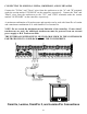
PLANNING It is very important to plan where the OmniTouch 5.7 Touchscreen will be installed and the gauge/type of wire you will use for the installation. The touchscreen can be connected directly to the HAI controller if video is not being used. However, if video is being used, the touchscreen must be connected to the HAI Touchscreen Hub. The HAI Touchscreen Hub can also be used if you are connecting multiple touchscreens (up to 8).
If cable with multiple conductors is used (such as Cat-5 cable), it is possible to connect multiple conductors together to achieve greater distance. For example, using only one of the 24 gauge conductor in the Cat-5 cable for power (1 for positive and 1 for ground), the maximum distance between the controller and the touchscreen is 113 feet.
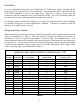
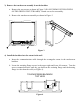
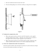
INSTALLATION 1) Make the cutout for the touchscreen Hold the template (Installation Template – 53A10-1) against the wall so the top edge is at the appropriate height and parallel to the floor. Using a Punch, or similar instrument, punch through the center of each tick mark (+) on the template. Drill a 1/4" hole at each punch mark. Using a pencil, draw a line around the quadrant of each hole as shown as shown. Carefully cut along the pencil line.
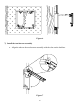
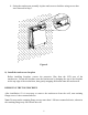
3) Remove the touchscreen assembly from the backbox a. Remove the two screws as shown in Figure 3 (DO NOT REMOVE THE SCREWS ON THE GREEN CIRCUIT BOARD). Retain screws for reassembly. b. Remove the touchscreen assembly as shown in Figure 3. Figure 3 4) Install the backbox into the cutout in the wall a. Insert the communications cable through the rectangular cutout in the touchscreen backbox. b. Locate the retaining flange screws in the upper right and lower left corners.
c. Place the assembled unit into the cutout in the wall. d. Turn the retaining flange screws clockwise until they are snug (do not over tighten). WALL Figure 5 5) Terminate the communications cable a. When connecting the touchscreen directly to the HAI controller, use the supplied 8-position modular cable assembly. Attach the wires coming from the controller to the supplied cable assembly using the supplied wire spice connectors. b.
Figure 6 7) Install the touchscreen assembly a. Align the tabs on the touchscreen assembly with the slots on the backbox.
b. Swing the touchscreen assembly in place and secure to backbox using screws that were removed in Step 3. Figure 8 8) Install the touchscreen faceplate Before installing faceplate, remove the protective film from the LCD area of the touchscreen. Fasten the faceplate onto the touchscreen by hanging the top of the faceplate on the top edge of the touchscreen, then gently snapping the bottom onto the touchscreen.
CONNECTING TO OMNI IIe, LUMINA, OMNIPRO II, AND LUMINA PRO Connect the "Yellow" and "Green" wires from the touchscreen to the "A" and "B" terminals under the section marked "CONSOLE" on the controller, respectively. Connect the "Red" and "Black" wires from the touchscreen to the "12V" and "GND" terminals under the section marked "AUXILIARY" on the controller, respectively.
CONNECTING TO OMNILT Connect the "Yellow" and "Green" wires from the touchscreen to the "YEL" and "GRN" terminals under the section marked "CONSOLE" on the controller, respectively. Connect the "Red" and "Black" wires from the touchscreen to the "12V" and "GND" terminals under the section marked "AUX" on the controller, respectively. A maximum combination of 4 touchscreens and consoles can be used with OmniLT. NOTE: Do not exceed the maximum current limitation of the controller.
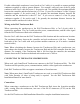
ADDRESSING THE TOUCHSCREEN OmniTouch touchscreens are connected to the same communications bus as HAI consoles. Each console and touchscreen must have a unique address. The default address setting of the touchscreen is "1". When power is first connected to the touchscreen, if the touchscreen isn’t addressed properly (other consoles or touchscreens already occupy the touchscreen address) or isn’t communicating with the controller, the following page is displayed.
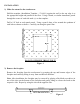
Brightness and Contrast Press the [up arrow] button to raise the current brightness or contrast setting. Press the [down arrow] button to lower the current setting. Video If the touchscreen is connected to the HAI Touchscreen Hub with Video Encoder, press the [up arrow] button to enable video on the touchscreen. If not, press the [down arrow] button to disable video. When Video is enabled, the Video icon will be displayed on the Home page. If it is disabled, the Setup button will be displayed instead.
UPDATING THE TOUCHSCREEN The USB Update Port on the OmniTouch 5.7 allows you to update the touchscreen with the latest firmware and screens. This allows you to take advantage of new touchscreen features and new screens that support features of updated controller firmware. The Update Port is a USB port in the lower right section of the touchscreen. USB UPDATE PORT Load the update file on a USB thumb drive. Plug the thumb drive into the USB Update Port on the OmniTouch 5.7 Touchscreen.
SPECIFICATIONS Size: Backbox cutout: Faceplate: LCD View Area: 5.625" W x 5.125" H 6" W x 5.5" H 4.626" W x 3.