
- HAI OmniPro II Owner's Manual
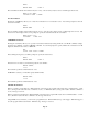
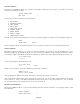
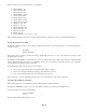
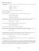
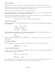
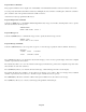
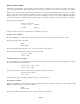
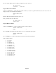
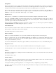
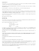
Table Of Contents
- INTRODUCTION
- OVERALL DESCRIPTION
- SECURITY SYSTEM OPERATION
- Disarming the Security System and Silencing Alarms
- Arming the Security System
- Using Shortcut Keys
- Quick Arm
- Bypassing Zones
- Restoring Zones
- What To Do When You Come Home
- What Happens When the Alarm is Activated
- Emergency Keys
- Duress Code Entered or Duress Alarm Activated
- Alarm Reset
- Alarm Cancel
- Trouble Indications
- Codes
- Duress Code
- Panic Switches
- Area Arming
- GOTO Area
- Testing Your System
- CONTROL
- Control Commands
- About UPB
- HAI Lighting Control (HLC) Format
- About CentraLite
- About Lutron RadioRA
- About ALC
- About X-10
- House Codes
- Unit Numbers
- Scrolling Through Names
- Controlling Units
- Timed Commands
- Status of a Unit
- Internal Flags
- Controlling Outputs
- All On / Off
- Leviton Scene Control
- Buttons
- Temperature Control
- HAI RC-Series Thermostats
- Programmable Energy Saver Modules (PESMs)
- Temperature Alarms
- Humidity
- Status
- Event Log
- Messages
- TELEPHONE CONTROL
- Telephone Interface
- In-House Phones
- Remote Phones
- Phone Access Denied - Remote Lockout
- Alternate Method
- Main Menu
- 1 - Control
- 2 - Security
- 3 - Button
- 4 - All
- 5 - Temperature
- 6 - Status
- 7 - Events
- 8 - Message
- 9 - Good-Bye
- Panic Button over the Phone (# # # # # #)
- Emergency Dial-Out
- Digital Dialer
- Voice Dialer
- PC Access
- Built-In Ethernet Port
- Controller IP Address, Port Number, and Encryption Key
- OmniPro II Ethernet Connections
- Connecting to Network via PC Access
- Dynamic DNS
- SETUP
- UNDERWRITER'S LABORATORIES REQUIREMENTS
- FEDERAL COMMUNICATION COMMISSION NOTICE:
- CANADIAN INDUSTRY CANADA NOTICE
- APPENDIX A - DIAL OUT PLANNER
- APPENDIX B - TEXT DESCRIPTION CHARACTER CODES
- APPENDIX C - VOICE DESCRIPTION CODES
Edit Program Command
Selecting 2 (CMD), from the Edit Program menu, allows the commanded action for the program to be specified. The following
menu is displayed:
1=CONTROL 2=SECURITY
3=BUTTON 4=ALL
↓
5=TEMP 6=ENERGY
8=MESSAGE ↑
After the command is specified, the display returns to the Edit Program menu:
Program Control Commands
Press the 1 (CONTROL) key to command lights and appliances. Specify the desired command - See Control.
Porch Light (Unit Name)
0=OFF 1=ON 2=DIM 3=BRT
↓
Porch Light (Unit Name)
4=LVL 5=RMP 9=TIM #=STA
↑
If the selected unit is part of a House Code that is configured to use the Compose Format, the second page of the menu is
modified to allow Scene commands. Consequentially, the Level and Ramp Commands are removed from the menu.
Entry Lights (Unit Name)
4=SCN 9=TIM #=STA
↑
If the selected unit is not capable of dim and bright commands, only a single menu is shown.
Porch Light (Unit Name)
0=OFF 1=ON 9=TIM #=STA
If the selected unit is UPB, press 6 (LED) to control an LED on a UPB Keypad.
On the 6-Button Keypad: LED 1 is behind the “On” button, LED 2 is behind the “Off” button, and LED 3-6 is behind the A-D
buttons, respectively. On the 8-button Keypad: LED 1-8 is behind the 1-8 buttons, respectively. For example:
WHEN U1 SW 3:
UNIT 1 LED 3 ON
This program illuminates the “A” button (on a 6-Button Keypad) when the “A” button on that keypad controller is pressed. This
program can also be used to illuminate the “3” button (on an 8-Button Keypad) when the “3” button is pressed.
If the selected unit is UPB, the # (STA) key is used to request the status form the specified UPB device.
WHEN LINK 1 ON:
Porch Light STATUS
When “Link 1 On” is received on the UPB network, OmniPro II sends a status request message to the UPB Wall Switch (named
Porch Light) to acquire its current status.
This “Status Request” program is particularly beneficial to keep the current state of UPB devices that are altered by a “lighting
scene” (Link On or Link Off) command. When the Link On or Link Off command is transmitted by a 6-Button or 8-Button
Keypad Controller, each device that has that Link pre-configured will respond to its preset levels. At this point, OmniPro II no
longer knows the exact state of the units that responded to the specified Link command until the switch is pressed locally, the
controller sends a command message to the device, or a Status Request message is issued to the device.
Page 66