HOME AUTOMATION, INC. Model 68A00-1 Network Digital Video Recorder (DVR) Installation and User Guide Document Number 68I00-1 Rev.
CONTENT VERIFICATION Before installing the Network Digital Video Recorder, please make sure that the following items are included in the box: 1. Network Digital Video Recorder 2. Crossover LAN cable 3. DC 5V / 1.5 A Power Adapter 4. Terminal Block 5. Client Software CD 6.
DISCLAIMER • While every effort has been made to ensure that the information contained in this guide is accurate and complete, no liability can be accepted for any errors or omissions. • HAI reserves the right to change the specifications of the hardware and software described herein at any time without prior notice.
FCC NOTICE Network Digital Video Recorder, Model 68A00-1: This device complies with Part 15 of the FCC Rules. Operation is subject to the following two conditions; 1. This device may not cause harmful interference, and 2. This device must accept any interference received, including interference that may cause undesired operation. Note: This equipment has been tested and found to comply with the limits for Class B digital devices, pursuant to Part 15 of the FCC rules.
Read this First Test Sessions Before you try to record important subjects, we highly recommend that you make several test recording and playback sessions to ensure that the Network Digital Video Recorder is operating and being operated correctly.
SAFETY PRECAUTIONS • Before using the Network Digital Video Recorder, please ensure that you read and understand the safety precautions described below. Always ensure that the Network Digital Video Recorder is operated correctly. • The safety precautions noted on the following pages are intended to instruct you in the safe and correct operation of the Network Digital Video Recorder and its accessories to prevent injuries or damage to the self, other persons and equipment.
• Do not allow the equipment to come into contact with, or become immersed in, water or other liquids. Do not allow liquids to enter the interior. The Network Digital Video Recorder has not been waterproofed. If the exterior comes into contact with liquids or salt air, wipe it dry with a soft, absorbent cloth. In the event that the water or other foreign substances enter the interior, immediately turn the Network Digital Video Recorder’s Power off or unplug the power cord from the power outlet.
• The supplied power supply and power cord are designed for exclusive use with the Network Digital Video Recorder. Do not use it with other products or battery. There is a risk of fire and other hazards. CAUTION • Avoid using, placing or storing the equipment in places subject to strong sunlight or high temperatures, such as the greenhouse or trunk of a car. Exposure to intense sunlight and heat may cause the battery to leak, overheat or explode, resulting in fire, burns or other injuries.
Warnings Open the cover at your own discretion. or electric shock. product. Doing so can cause system damage Contact a qualified technician or your dealer for repair of this Manufacturer is not responsible for any damage or injury sustained by opening and/or assembling/disassembling the unit. Electric shock or fire may result when foreign liquids or substances are introduced into the unit. If this occurs, discontinue use, power down the unit and contact your dealer immediately.
Table of Contents CONTENT VERIFICATION........................................................................................................... 1 DISCLAIMER ................................................................................................................................ 2 FCC NOTICE................................................................................................................................. 3 Canadian Radio Interference Regulations.........................................
2. The 68A00-1 Viewer ...................................................................................................... 25 2.1 Image Display Panel ............................................................................................... 25 2.2 Video Control Panel ................................................................................................ 26 2.4 Go to Admin page ................................................................................................... 29 2.
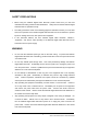
NETWORK DIGITAL VIDEO RECORDER LAYOUT 1. FRONT LAYOUT ⑤ ① ④ ③ ① ② Ready LED Indicates the unit is completed initialized and is ready to be accessed. ② On Air LED Indicates that one or more users are connected to the unit. ③ Audio Input/Output Connector Connect a speaker to the output. Input allows connecting an audio device with audio input level of 0.2-2V (line-in level normally). ④ RS-232 port The RS-232 port is used as console monitoring or can be used as an external signal input port.
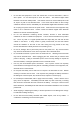
2. REAR LAYOUT ⑤ ④ ③ ② ① ① Power Input connector (DC 5V) * Please check the voltage of your connecting adapter. ② Ethernet port (10/100 Base-T Ethernet) ③ Data I/O connector Sensor Input connector (S1, G, S2): Connect up to 2 dry contact input sensors. Data Output (DO) connector (NC, NO, COM): Normally Open (NO) type or Normally Close (NC) type may be used. RS-485(+, -): Connect pan, tilt, and zoom available camera or unit. ④ Video Out One channel composite video output is supported.
Warning: Ensure that you are using the right adapter for the power. Otherwise, fatal damage will be caused to the unit. In such case, HAI is NOT responsible for the damage. 3.
3.
I. Introduction 1. Network Digital Video Recorder The 68A00-1 Network Digital Video Recorder is a device that transmits video and audio data via network in real-time. The server converts the analog video signals and audio signals into digital data and compresses them for on-line transmission. Since the server has a built-in web server and network interface, it may not require additional hardware, software, or programming (besides configuring IP address) to view live video transmissions.
3. Main Features The 68A00-1 is designed for various applications, such as IT related applications, remote monitoring, and Internet broadcasting with the user friendly interface. Highly Efficient MPEG4 Video Compression The 68A00-1 support a 4 to 5 times more efficient transmission compared to similar products based on the existing still image compression methods (JPEG and Wavelet). Under the same conditions, if the size of motion pictures and audio by still image compression method is 7.0 - 8.
Local Recording and Playback The internal hard drive provides the total security solution via network. 68A00-1 stores live video and audio on its local drive. The You can search and playback files at any time and anywhere network access is available.
II. Installation This chapter covers installation of the 68A00-1 Network Digital Video Recorder on Static IP environments. Refer to Chapter 5 for more information about the installation on Dynamic IP environments. 1. Connect the 68A00-1 to a configuration PC: 1.
2.2 Browsing the 68A00-1 unit Click the ‘Search’ button to detect the 68A00-1 unit on the same subnet. The 68A00-1 will be shown with its MAC Address, the factory default IP Address, Subnet Mask, and Gateway, as seen below: IP Address: 192.168.1.2 Subnet Mask: 255.255.255.0 Gateway: 192.168.1.1 Select the 68A00-1 to be installed and set the IP address, subnet mask, default gateway and administrator’s password (that is set as ‘pass’ for factory default) followed by clicking the ‘Set’ button.
When changing ‘Http Port’ or ‘Streaming Port’, it is necessary to restart the Unit by clicking ‘Restart the server’. The value of ‘Streaming Port’ has to be set with a modulo of 10 plus 1 (e.g. 7011, 7021, 7031, etc.).
2.3. Confirm communications To confirm communications, click the ‘Ping test’ button. Confirmation of communications should look similar to the following: Reply from 192.168.1.2: byte=32 time=2ms TTL=225 Reply from 192.168.1.2: byte=32 time=2ms TTL=225 Reply from 192.168.1.2: byte=32 time=2ms TTL=225 Reply from 192.168.1.
III. Real-time Video Monitoring 1. Accessing the 68A00-1 Server Run Internet Explorer 4.0 or higher on the PC, and enter the IP address of the 68A00-1 unit into the address bar. 1.1 Auto-installation of the Client Viewer Program When initially accessing the 68A00-1 home page, the client viewer software is automatically downloaded and installed to allow you to view the MPEG-4 video images. As noted in Chapter 3, the Active-X Control Plug-In should have been installed on the browser.
If video is not displayed, ensure that the camera and network cables are properly connected on 68A00-1 unit. If trouble persists, please refer to Troubleshooting in Appendix 1. 1.2 User Login The default login for users is ’guest’ for both ID and Password. The system administrator can modify the ID and Password and assign an individual ID and Password to each user. The login page allows the user to choose between the 68A00-1 Viewer and the 68A00-1 Player.
The 68A00-1 user’s log in page will be displayed. The Default Guest Account ID and Password are both “guest”. NOTE: The 68A00-1 browser interface requires the Active-X Control Plug-In for Internet Explorer. If the Active-X Control Plug-In is not installed, you will be prompted to install the plug-in before the 68A00-1 interface is launched. answer “YES” to the questions about installation of the plug-in.
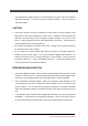
2. The 68A00-1 Viewer When the installation of the client program is complete and your login is accepted, the 68A00-1 Viewer is automatically connected and begins displaying video. <68A00-1 Viewer> 2.1 Image Display Panel The image display panel can display up to 4 channels. of 320x240. Each channel has a resolution The display panel has the following components. Title Bar Displays the title of the channel as entered in Administration.
Title Bar 2.2 Video Control Panel The control panel allows the user to control camera options. Camera Selection Camera Selection allows you to selects a single channel for view/display. View Selection View selection allowsyou to configure the channel display mode.
Single channel display Displays the selected channel. Quad channel display Displays 4 channels simultaneously. Full screen display Zooms in the single channel to fill the display area. Sequence channels Will be sequenced at every 5 seconds (Duration time is fixed). Pause/Play Button Pause Stops transmitting video images (button then changes to the Play button). Play Resumes transmission of the video images.
2.3 PTZ Control Panel The PTZ control panel allows users to control the basic functions supported by PTZ cameras, including pan, tilt, zoom, auto pan, focus, auto focus, and location presets. PTZ control is only allowed to those users whose ID is authorized to control PTZ cameras.
2.4 Go to Admin page The Admin button brings you to the login screen for the Administration page for the 68A00-1. Setup is described in the next chapter. 2.5 Audio mute The Audio button will enable or mute audio sound. The default button display is ON. 2.6 Transfer to 68A00-1 Player Click this icon to open the 68A00-1 Player window.
IV. Search and Playback 1. Remote Playback The 68A00-1 stores live video and audio on the internal hard drive. It is possible to connect to the Video On Demand (VOD) like file server, using the friendly web interface, with no additional program installation. Users can access the server for playback of the recorded files whenever and wherever network access is available. operation is shown in the following figure. simultaneously on the multi-functional viewer.
3. 68A00-1 Player If a user accesses the 68A00-1 Player, the following multi-functional viewer appears and an initial search is performed. The display shows the file list and time-map of the current day. <68A00-1 Player> The 68A00-1 Player mainly consists of the image display panel, playback control panel, intelligent time-map panel, calendar, file list panel, and display mode panel. two ways of file playback.
3.2 The time-map Panel and intelligent playback The 68A00-1 supports seamless playback using a time-map concept. the colored map, showing the file existence in a whole day range. Time-map is There is a different color for each attribute, as follows: , , , , . To playback files using intelligent playback, move the cursor to the time position of the file to be played back, and then click the play button.
3.3 Playback Control Panel The playback control panel consists of playback related control buttons. File Open Backward Fast Backward Pause Step Backward Play Step Forward Stop Fast Forward Speed Scroll Rec Play and Backward Start playback and reverse direction. In the intelligent playback first move the cursor where you want start. Step Forward and Step Backward Step-by-step playback in forward and reverse direction. Fast Forward and Fast Backward 2 times fast forward and reverse playback.
3.5 Storage gauge Storage gauge shows the usage of the storage device. In case of a problem or failure of the storage device, the storage fail message, will appear. 3.6 Search, Backup, and Print Search Print Backup Search Search the file list and get the time-map on the selected day. is selected and the file list is searched automatically. The present date In order to get the file list of another date, select the desired date from “Calendar” then click “Search” button.
The Backup dialog box will appear and show the progress. Multiple file backup is allowed. Print: Print the current display area. 3.7 File List Panel The File list panel lists recorded files on the select day. The status icon helps you identify the attribute of files when the file is generated. meanings of the each icon are “ Signal”, “ Motion”, and “ Live”, “ Network Fail”, “ Sensor”, “ The No Continuous”.
To search files from another day, select the desired date on the calendar, and then click search button. 3.8 View Channel Mode Selection Panel The buttons on this panel change the mode of the image display panel. Single View 8-ch view Full screen 16-ch view 4-ch view 3.9 Configuration The Configuration button launches the 68A00-1 Player configuration dialog.
3.10 Go to the Administrator’s Page The Admin button is used to access the login screen for the Administration page. Device related setup is described in the next chapter. 3.11 Go to the 68A00-1 Viewer To access the 68A00-1 Viewer directly, click this icon.
V. Setup 1. Connect to the Administration Page To program or to change any configuration of the 68A00-1 Network Digital Video Recorder, you must access the web-based Administration Page. There are two ways to connect to the Administration Page: Press the Admin button from the User interface and enter the proper ID and Password. -orIn the Internet Explorer address bar, type: http://xxx.xxx.xxx.xxx/admin_login.html (where xxx.xxx.xxx.
2. Management of System Setup 2.1 General Settings * Setting Date and Time Select the appropriate Date and Time then make sure to click the Set icon. * Use the following Public Time Server (port: 123) : If available, type in the primary and the secondary time server’s IP address.
* User Management Administrator After setting the new admin password, make sure to click the SAVE icon. Add User The 68A00-1 Network Digital Video Recorder allows multiple user accounts with multiple levels of authorization. User ID Enter the login ID for a user. Password Enter a password for the user ID. Confirm (password) Confirm the password.
User List Under User List, it is possible to modify information of existing user accounts. Additionally, it is possible to delete existing user accounts. Priority • Set the priority level of each account. • Note that the higher number is a higher priority. • If two users with different priority levels connect simultaneously, the higher priority user takes authority over the lower priority user. Note that Admin takes any authority over any Users.
2.2 Video Settings * Video Channel Control Video Channel Control is used to activate the channels, to set the image quality, resolution, camera title, and encoding frame rate. Enable • Select the channel that is going to be in use. Quality • Choose between VBR and CBR. • VBR consists of Lowest, Low, Normal, High, and Highest. • CBR can adjust the bit rate. The bit rate tab is activated only after CBR is selected.
Title Enter the title for each camera into this box, up to 255 characters in length. * Color control Numeric values of Brightness, Hue, Saturation, and Contrast can be programmed for each camera channel. * Video Type Select the proper video signal type between NTSC and PAL. The change will be applied after restarting the unit. * Buffer Size Select the size of the buffer that the unit will buffer while transmitting the images. Make sure to click Save after making any adjustments.
* Motion Detection Sensitivity (%) Select the appropriate sensitivity level. Area setting Select the area that motion needs to be detected.
2.3 Audio Settings Enable Check the box if audio is being used. Related Video Channels Click on the specific channel(s) that is associated with audio. All channels can be selected. Note that sound will be audible only when a selected video channel is displayed in the Live view screen. Enable If you are going to use interactive audio, check the Enable box.
2.4 Pan/Tilt/Zoom (PTZ) Setup * Channel selection Choose the channel for PTZ setup from the drop-down list. * Pan/Tilt/Zoom Device Settings Enable Enables PTZ control for the selected channel. Manufacturer (Model) Choose the manufacturer and the model for PTZ camera from the drop-down list. Device ID Enter the ID of the PTZ camera. PTZ camera. This ID should match the physical ID set on the Please refer to the PTZ camera manufacture’s instruction manual for setting up physical ID.
Tilt Speed Enter the speed for the dome to move up and down. This range may vary from device to device. Halt Speed Enter the delay time before the dome reverses direction when auto-panning. This range may vary from device to device. * Auto Pan/Preset Settings Auto Pan To set the start and end points for auto-panning, move the camera to the start point of the sweep, select Point 0 from the drop-down list, and click the Set button.
2.5 Schedule On the schedule page, different types of events can be defined and the related actions can be specified. “Network Fail”. There are four types of events: “Sensor”, “Motion”, “No signal”, and Related actions are: “Relay control”, “Recording”, “E-mail notification”, and “Notification to event server”. Weekly scheduling The 68A00-1 supports weekly based schedule recording. recordings that are triggered by events.
Follow these steps for schedule reservation and event notification: 1. Check the type of Event and create the schedule (multiple selections are possible) : Left mouse button: Draw : Right mouse button: Erase 2. Create an event 3. Assign the video channel to record 4. Specify the action and notification triggered by that event Network Fail Assign the server to generate the “Network Fail” event when the connection is lost between the 68A00-1 and this server.
The types of Event * Sensor Event Set a duration time, record channel, pre-alarm, post-alarm, and type for each sensor. * Motion Detection Event When configuring motion detection, it is possible to include a relay output, duration, record channel, pre-alarm, and post-alarm. * No signal (Video loss) Event If the video transmitted from the 68A00-1 is lost or damaged, a “No signal” event occurs.
* Network Fail Event If the network connection between the 68A00-1 and the server assigned in the “Network Check Server” is lost, a “Network Fail” event occurs. Actions and Notifications * E-mail Notification E-mail notifications can be sent up to five e-mail addresses. Attaching Snapshot is NOT supported.
* Notification to the Event server Up to five Event Servers can be created. be sent. The event type and the time of incident will The actions, according to the event, are defined at the event server. 2.6 Network Settings Additional network parameters can be configured after the initial setup using the IP Setup Wizard. WARNING: Consult with the network administrator before making any further changes to the network settings.
Refer to the below for proper configuration for each service type. On Static IP 1) Click “Use the following IP address”. 2) Set the IP Address, Subnet Mask, and Default Gateway. 3) Click ‘Save’. 4) Click ‘Restart’. (Setting will be applied after rebooting is completed) On Dynamic IP 1) Click “Obtain an IP address automatically using” then select between ADSL, requiring User ID & Password, and DHCP. 2) If necessary, set the User ID & Password provided by the ISP. 3) Click ‘Save’. 4) Click ‘Restart’.
* Streaming Port Settings The default streaming port setting is 7011. conflict. However, it can be changed in case of port The streaming port setting has to be a modulus of 10 plus 1 such as 7011, 7021, 7031. * Modem Power Control When the network connection has a problem, the server gives an automatic restarting signal to modem power for reconnection to the Network. * Ethernet Settings The modem can have different link types. modem type.
2.
For Dynamic IP service users, it is possible to register the 68A00-1 Network Digital Video Recorder with a DDNS server. This will give those with Dynamic IP service a convenient way to connect to the 68A00-1 since the DDNS Server checks the IP address of the 68A00-1 for you. Registration settings: Server IP Enter the Directory Server IP address Logon ID Enter the ID of 68A00-1 registered to the directory server. Logon Password Enter the password.
2.8 D/O control (Relay Control) The 68A00-1 has up to 4 digital output (DO or Relay) terminals. If the duration period is 0, the output will turn ON or OFF, indefinitely. On the other hand, if the duration period is set to something other than 0, it is ON for the specified period of time, and then turns OFF automatically. To execute relay control, you must have authority for “PTZ control”. Warning: The maximum input voltage for a relay is 24V (1A). 2.
2.10 Configuration Import/Export The 68A00-1 Network Digital Video Recorder allows you to import and to export device configuration. This may also be used for programming multiple 68A00-1 Network Digital Video Recorder devices. To import saved settings, click Browse, locate the saved file from local disk, and then click Import. Choose the particular settings that need to be exported or click Select All then click Export. When prompted, set the proper file name.
2.11 Software Update This page allows an administrator to upgrade the server software. * Current Software Version This section allows you to confirm the current software version installed in the 68A00-1. After completing the update, check this section again to ensure 68A00-1 recognizes the new software. * Upload Update File This section is used to perform the actual software update. o Copy the latest Update file received from HAI technical support to a PC being used to accomplish the Upgrade.
Warning: The 68A00-1 Network Digital Video Recorder system software upgrade option is available from any network that can access the server. However, while updating, if the power to the unit goes out or if the network gets disconnected, the unit may malfunction. 2.12 Restart If you want to restart this system, you can invoke a restart manually in this section.
Appendix 1: Troubleshooting Ready LED is not ON. Ensure that the current network configuration is ADSL or DHCP. The ‘Ready LED’ is only on for these configurations. After five minutes with ‘Ready LED’ off, the 68A00-1 unit reboots automatically. Change network configuration to Static IP. Ping does not respond from specified IP address. Ensure that the 68A00-1 and installing PC are on THE SAME SUBNET. The error message “Can not find web-page” is displayed when attempting to access the server.
No audio is heard even if microphone is installed Confirm whether the microphone is properly installed in Audio ‘IN’. from the source must be Line-Level. The output If the output from the source is too low to be heard, the source must be amplified to achieve Line-Level. Ensure that the audio function is enabled on the Admin page. Ensure that the audio button on the bottom right of main viewer is activated.
Notes 63 68A00-1 NETWORK DIGITAL VIDEO RECORDER
Notes 64 68A00-1 NETWORK DIGITAL VIDEO RECORDER
Notes 65 68A00-1 NETWORK DIGITAL VIDEO RECORDER