#11034 Kakute F7 AIO User Manual & Installation Guide v1.
Contents Overview .......................................................................................... 1 Features Specifications Warranty and Return Policy Pinout Diagram .............................................................................. 4 Installation Guide ......................................................................... 5 Updating Betaflight Firmware .............................................
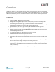
Overview The Holybro Kakute F7 All-In-One flight controller makes it easy to build your multirotor. It integrates flight controller (FC), power distribution board (PDB), and on-screen display (OSD) in one. The Kakute F7 AIO’s layout makes it easy to wire up the other components of the multirotor while keeping the build neat and tidy. Features • • • • • • • • • • • • Supports Betaflight, Butterflight, and Cleanflight. Betaflight OSD.
Specifications • • • • • • • • • • • • MCU: STM32F745 32-bit processor IMU: ICM20689 (SPI) Barometer: BMP280 Current Sensor: Approximately 130 amps maximum measurable value USB VCP Driver (all UARTs usable simultaneously; USB does not take up a UART) 6 hardware UARTS (UART1,2,3,4,6,7) All UARTS support hardware inversion. SBUS, SmartPort, and other inverted protocols work on any UART without “uninvert hack”. Supports serial receivers (SBUS, iBus, Spektrum, Crossfire) only.
Warranty and Return Policy If you believe that your Kakute F7 AIO is defective, please contact us. If we determine that the board is defective, it will be repaired or replaced at no charge to you. We may ask you to send your Kakute to our service center for examination or repair. Shipping costs are your responsibility. Returned items should include the original packaging and all accessories. If product is damaged or defective, we will repair or replace it.
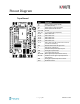
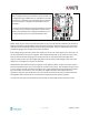
Pinout Diagram Top of board Pin Function B+ 5v VO VI G or GND SDA, SCL R1, T1 R2, T2 R3, T3 R4, T4 R6, T6 R7, T7 Battery positive voltage (2S-6S) 5v output (2A max) Video output to video transmitter Video input from FPV camera Ground 2 I C connection (for peripherals) UART1 RX and TX UART2 RX and TX UART3 RX and TX UART4 RX and TX UART6 RX and TX UART7 RX and TX (RX is located at corners for use with ESC telemetry) WS2182 addressable LED signal wire Piezo buzzer ne
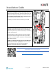
Installation Guide Solder the main battery connector to the large + and - pads on the board. The battery connector should use either 12 gauge or 14 gauge, fine-strand, silicone-insulation wire. This type of wire is commonly referred to as “silicone wire”. Do not use regular stranded copper wire for the battery lead. It will become brittle over time and break. The battery connector will most commonly be an XT60. Install the Kakute F7 AIO in your quadcopter frame.
Solder the ESC power wires to the G and B+ pads at the corners of the Kakute F7 AIO. ESC power wires are typically 18 or 20 gauge. Some ESCs are sold without attached wires, in which case you will need to provide your own. We recommend 20-gauge silicone wire for this purpose. Each ESC should be soldered to the pads in the corner closest to it. Cut the wires short to eliminate excess wire that can get caught up in props, but be sure to leave yourself a little slack.
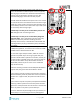
Telemetry allows the Kakute F7 AIO to report values, such as battery voltage, back to your transmitter. The transmitter can be configured to give audible alerts on low battery, and other such functions. Telemetry is also useful because it allows the use of “Lua Scripts” to configure the quadcopter from the transmitter. If you intend to use telemetry, solder the telemetry wire from your receiver to the T4 pad on the Kakute F7 AIO. On FrSky receivers, the telemetry wire is labeled as SmartPort.
Solder the video wire from the video transmitter (vTX) to the VO pad on the Kakute F7 AIO. Solder the video wire from the camera to the VI pad on the Kakute F7 AIO. Depending on whether you intend to run off vBat or 5v, solder the power wire for the camera and vTX to either the 5v or the B+ pad nearest to where you soldered the video wire. Solder the ground wire from the camera and the vTX to the G pad nearest to where you soldered the video wire.
How to wire up analog RSSI to your receiver https://www.youtube.com/watch?v=pX_PWoLhooU An alternate way to get RSSI in your OSD https://www.youtube.com/watch?v=t-evOAS9Mkg Some ESCs support a feature called ESC Telemetry. This feature allows the ESC to report data such as motor RPM and amps being used by the ESC back to the flight controller. The main advantage of this feature is when the flight controller does not have built-in current monitoring.
FPV Camera Control is a feature of Betaflight that allows you to access your FPV camera’s on-screen menu using your transmitter sticks. With this feature, you can easily adjust brightness, contrast, and other camera settings in response to changing lighting conditions. There are two forms of Camera Control: analog and digital. Analog camera control is for cameras that use an analog-style joystick input. Digital camera control is currently reserved for some Runcam cameras.
Updating Betaflight Firmware Like all software, the software that runs your flight controller has versions. Just like Windows XP was followed by 2k, then 7, 8, and 10. The software that runs your flight controller is called Betaflight. Putting a new version of Betaflight on your Kakute F7 AIO is called “flashing” your board. Even if you decide you don't want to update your firmware right now, you still need to install the VCP driver to configure the board.
The video linked above shows a process of using Zadig to replace the VCP driver. The ImpluseRC Driver Fixer is an easier way of doing the same thing. So, use the ImpulseRC Driver Fixer and don’t mess around with Zadig like the video shows. Is It Over Yet? THAT WAS SUPER ANNOYING WASN’T IT. Yes… we know. The good news is, you do not need to repeat this process again. Sort of. You never need to install the drivers again on this computer, unless you reinstall the operating system for some reason.
Flashing New Firmware At this point, if you want to update your firmware, here is how to do it. But if you just want to go fly, please, go for it! You don’t have to be running the absolute latest firmware to have a good time. Just forget about this nonsense! To flash your firmware, you must connect the board in “bootloader mode”. Bootloader mode means that the board is ready to accept new programming.
Here are the remaining steps: 1. Go to the “Firmware Flasher” tab. 2. Select “KAKUTEF7” in the “Choose a board” pulldown menu. If you flash any other board type, the Kakute F7 AIO will not function. It won’t be damaged, it just won’t work until you flash KAKUTEF7 to the board. 3. Select the latest version of Betaflight in the “Choose a firmware version” pulldown menu. 4. Click the “Load Firmware (Online)” button. The button will change to read “Downloading”.
Initial Configuration The full configuration of Betaflight could take hours to document. In this section, we’ll describe a few things that are specific to this board. This won’t be enough to get you into the air, so we’ll also point you to some videos you can watch if you’re not perfectly sure what else you need to do. Even people have a few builds under their belt may be skipping some important steps without realizing it! Connect to The Board Plug the board in to USB.
For each function, identify which UART number you connected the peripheral to. So if you soldered your receiver signal wire to pad R3, that would be UART3. If you soldered your SmartPort telemetry wire to pad T1, that would be UART1. The number following the R or T indicates the UART number. On each row in the Ports tab, enable the one function that you connected ot the TX and/or RX pads for that UART. The most common options are below.
Configuration Click on the “Configuration” tab on the right side of the window. Scroll down to the “Other Features” section. • • • • • • If you are using any kind of telemetry (SmartPort, Crossfire, etc.), enable TELEMETRY. If you are using a programmable LED strip, enable LED_STRIP. Air Mode increases authority when the throttle is all the way down. We recommend leaving this option on all the time. The Kakute F7 AIO has built-in Betaflight OSD. The OSD option should always be enabled.
Blackbox If you have enabled the Blackbox feature, go to the Blackbox tab on the left-hand side of the configurator window. In the Blackbox tab, at the top, set the Blackbox logging device to “SD Card” (it should be set like this by default). Set the Blackbox Logging Rate to 2 kHz. To use Blackbox logging, insert a FAT-formatted SD card of 32 GB or smaller into the SD card slot on the Kakute F7. You can use the Betaflight Blackbox Log Viewer app to examine blackbox logs.
OSD In the OSD tab, you can choose which values you want to see on screen while you are flying. Enable and disable individual elements using the Elements toggles on the left. The Video Format section lets you choose whether your camera is NTSC or PAL. Betaflight defaults this value to Auto, but Auto sometimes picks wrong. If this happens, you might not see any OSD text, or the bottom of the OSD text might be off the bottom of the screen. In some cases, you won’t see any video at all—just the OSD.
been allowed to rest at the end of a flight. If your batteries are consistently resting at below this level at the end of a day of flying, then you might be shortening their lifespan at least a little. mAh Drawn: Although voltage is what ultimately determines whether a battery is being damaged, mAh may be a better way of deciding when to land. Because voltage sags when you raise the throttle and recovers when you lower the throttle, it can be hard to tell exactly how used-up the battery is.
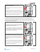
Using The OSD If you are using a Betaflight Flight Controller with Betaflight OSD, you can manage the Atlatl’s transmit power and channel from within the OSD. Mode 2 Mode 1 The graphics above show the stick command to bring up the OSD menu. The stick command is: throttle centered, yaw left, pitch forward. The exact stick command therefore depends on which mode your transmitter sticks are in. In the OSD menu, use pitch up/down to move the cursor between menu items.
The screen to the right shows the current vTX settings. From here, you can change the frequency band, channel, and power level of the video transmitter. After making the changes, move the cursor to “Set” and press roll-right to confirm the settings.
Using FPV Camera Control The Camera Control feature of Betaflight allows you to access your FPV camera’s setup menu using your transmitter sticks. To do this, you must have connected your FPV camera to the flight controller as described earlier in the manual. Here is how to use the Camera Control feature. With the quad disarmed, put the throttle at 50% (centered). Push yaw-right on the transmitter stick. You are now in Camera Control mode.
Saving Your Configuration Once you have finished building, configuring, and tuning your multirotor, it’s a good idea to back up your configuration so that you can restore it later. This is useful if you lose your quad, or if you damage your flight controller, or if you accidentally lock yourself out of your flight controller and must reset it to get back in. Before we show you the right way to save and restore your configuration, let us warn you about the wrong way.
Additional Reference Here are some links to additional videos to help you build your quadcopter successfully. Betaflight 3.3 Ultimate Setup Guide https://www.youtube.com/watch?v=8vJCrHj9s6s How to Calibrate Your ESCs https://www.youtube.com/watch?v=o3Mg-9M0l24 If you are using an analog protocol like Oneshot or Multishot, calibrating your ESCs is mandatory. Most ESCs today support Dshot. If your ESCs support Dshot, you should use it, and you can skip this step. Failsafe https://www.
Adjust PIDs / Rates / vTX from Taranis If you have a FrSky Taranis radio and if you are using telemetry (such as SmartPort, FPort, or Crossfire), you can use your Taranis to change your PIDs and rates. This is done by installing a piece of programming code called a Lua script on your Taranis. If you are also using SmartAudio, you can use a Lua script to change your vTX settings. This is the same as if you were using the Betaflight OSD, but it works without you having to put your goggles on.