#11031 Kakute F4 AIO (V2) User Manual & Installation Guide v1.
Contents Overview ....................................................................................................... 1 Features Specifications Warranty and Return Policy Pinout Diagram ........................................................................................... 4 Installation Guide ...................................................................................... 5 Updating Betaflight Firmware ..........................................................
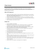
Overview The Holybro Kakute F4 AIO All-In-One flight controller makes it easy to build your multirotor. It integrates flight controller (FC), power distribution board (PDB), and on-screen display (OSD) in one. The Kakute F4 AIO V2’s layout makes it easy to wire up the other components of the multirotor while keeping the build neat and tidy. New V2 Features • • • • • Additional UART (UART 4) added to support serial camera communication such as to RunCam Split.
Specifications • • • • • • • • • • MCU: STM32F405RGT6 32-bit processor IMU: ICM20689 (SPI) Barometer: BMP280 USB VCP Driver (all UARTs usable simultaneously; USB does not take up a UART) 5 hardware UARTS (UART1,3,4, 5, 6) Supports serial receivers (SBUS, iBus, Spektrum, Crossfire) only. PPM and PWM receivers are not supported. 128 Mbit Dataflash chip for Blackbox logging Dimensions: 35x43x7mm (includes USB in height) Mounting Holes: Standard 30.
Warranty and Return Policy If you believe that your Kakute F4 AIO is defective, please contact us. If we determine that the board is defective, it will be repaired or replaced at no charge to you. We may ask you to send your Kakute to our service center for examination or repair. Shipping costs are your responsibility. Returned items should include the original packaging and all accessories. If product is damaged or defective, we will repair or replace it.
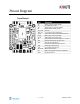
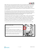
Pinout Diagram Top of board Pin Function B+ 5v VO VI G or GND SDA, SCL R3, T3 R4, T4 R6, T6 SP LED BUZ- RSSI 3V3 M1 to M4 RX Boot Battery positive voltage (2S-6S) 5v output (1.
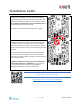
Installation Guide Solder the main battery connector to the large + and - pads on the board. The battery connector should use either 12 gauge or 14 gauge, fine-strand, silicone-insulation wire. This type of wire is commonly referred to as “silicone wire”. Do not use regular stranded copper wire for the battery lead. It will become brittle over time and break. The battery connector will most commonly be an XT60. Install the Kakute F4 AIO in your quadcopter frame.
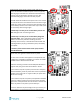
Solder the ESC power wires to the G and B+ pads at the corners of the Kakute F4 AIO. ESC power wires are typically 18 or 20 gauge. Some ESCs are sold without attached wires, in which case you will need to provide your own. We recommend 20-gauge silicone wire for this purpose. Each ESC should be soldered to the pads in the corner closest to it. Cut the wires short to eliminate excess wire that can get caught up in props, but be sure to leave yourself a little slack.
Before wiring up your camera and video transmitter (vTX), you must determine whether you will power them by 5v or battery voltage (vBat). Many cameras and video transmitters today can run off up to 4S (16.8 volts) without issue. Some cameras and video transmitters can run off even higher voltage. You must refer to the product specifications for your camera and video transmitter to determine what maximum voltage they allow.
Some video transmitters allow the channel, transmit power, and other such parameters to be configured remotely, through the Betaflight OSD. This means you can change channel and transmit power using your goggles and transmitter sticks, instead of pushing a button or flipping DIP switches on the vTX itself. This is a huge convenience! Holybro’s vTX, the Atlatl, as well as many others, use the IRC Tramp telemetry protocol to allow remote configuration.
RSSI monitoring allows you to view the signal strength of the control link between your transmitter and your receiver in the OSD. This can give a warning when you are getting close to the edge of your range, as well as showing you if you have damaged equipment, such as an antenna that has been cut by a prop. If you intend to use the RSSI input, solder the analog RSSI output of your receiver to the RSSI pad on the Kakute F4 AIO.
Updating Betaflight Firmware Like all software, the software that runs your flight controller has versions. Just like Windows XP was followed by 2k, then 7, 8, and 10. The software that runs your flight controller is called Betaflight. Putting a new version of Betaflight on your Kakute F4 AIO is called “flashing” your board. Even if you decide you don't want to update your firmware right now, you still need to install the VCP driver to configure the board.
The video linked above shows a process of using Zadig to replace the VCP driver. The ImpluseRC Driver Fixer is an easier way of doing the same thing. So, use the ImpulseRC Driver Fixer and don’t mess around with Zadig like the video shows. Is It Over Yet? THAT WAS SUPER ANNOYING WASN’T IT. Yes… we know. The good news is, you do not need to repeat this process again. Sort of. You never need to install the drivers again on this computer, unless you reinstall the operating system for some reason.
3. The configurator will start. To save time in the future, you can right-click the app icon in Chrome and choose “Create Shortcuts”. This will create shortcuts in your start menu and on your desktop, to launch the app directly. Flashing New Firmware At this point, if you want to update your firmware, here is how to do it. But if you are annoyed and frustrated at this point and just want to go fly, please, go for it! You don’t have to be running the absolute latest firmware to have a good time.
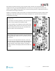
If your Kakute F4 AIO is in bootloader mode, then you will see “DFU” in the pulldown menu in the upperright of the configurator, as shown here: If you don’t see DFU in the pulldown menu, then either the board didn’t detect that you had the bootloader button pressed or your drivers are not installed correctly. If you don’t see DFU in the pulldown menu, you cannot flash new firmware to the board. It won’t work.
6. Flashing will be followed by a process called “Verifying”. Verification sometimes fails, but this isn’t a problem. If the flash completes, everything is usually fine. 7. Un-plug your board and then plug it back in again, this time without holding down the bootloader button. 8. For Windows users, the pulldown menu in the upper right of the configurator will read COM3 (or some other number). For MacOS and Linux users, the pulldown will read something starting with /dev/tty. This is normal.
Initial Configuration The full configuration of Betaflight could take hours to document. In this section, we’ll describe a few things that are specific to this board. This won’t be enough to get you into the air, so we’ll also point you to some videos you can watch if you’re not perfectly sure what else you need to do. Even people have a few builds under their belt may be skipping some important steps without realizing it! Connect to The Board Plug the board in to USB.
• • • If you are using RunCam Split remote control, on the UART4 line, in the Peripherals column, choose RunCam Split. If you are using ESC Telemetry, on the UART5 line, in the Sensor Input column, choose ESC. If you are using SmartAudio or ImmersionRC Tramp Telemetry to control your video transmitter: on the UART6 line, in the Peripherals column, choose either TBS SmartAudio or IRC Tramp, depending on which type of transmitter you are using.
Blackbox If you have enabled the Blackbox feature, go to the Blackbox tab on the left-hand side of the window. In the Blackbox tab, at the top, set the Blackbox Logging Rate to 1 kHz. OSD In the OSD tab, you can choose which values you want to see on screen while you are flying. Enable and disable individual elements using the Elements toggles on the left. The Video Format section lets you choose whether your camera is NTSC or PAL.
been allowed to rest at the end of a flight. If your batteries are consistently resting at below this level at the end of a day of flying, then you might be shortening their lifespan at least a little. mAh Drawn: Although voltage is what ultimately determines whether a battery is being damaged, mAh may be a better way of deciding when to land. Because voltage sags when you raise the throttle and recovers when you lower the throttle, it can be hard to tell exactly how used-up the battery is.
Using The OSD The Kakute F4 AIO includes Betaflight OSD, which displays information like battery voltage and mAh consumed while you fly. In addition, the Betaflight OSD can be used to configure the quadcopter, making in-field adjustments and tuning more convenient. Mode 2 Mode 1 The graphics above show the stick command to bring up the OSD menu. The stick command is: throttle centered, yaw left, pitch forward.
When a parameter can be modified, the parameter’s current value will be shown on the right-hand side of the screen. In this case, roll left/right will adjust the parameter up and down. The screen to the right shows the current vTX settings. From here, you can change the frequency band, channel, and power level of the video transmitter. After making the changes, move the cursor to “Set” and press roll-right to confirm the settings.
Saving Your Configuration Once you have finished building, configuring, and tuning your multirotor, it’s a good idea to back up your configuration so that you can restore it later. This is useful if you lose your quad, or if you damage your flight controller, or if you accidentally lock yourself out of your flight controller and must reset it to get back in. Before we show you the right way to save and restore your configuration, let us warn you about the wrong way.
How To Save and Restore Your Configuration https://www.youtube.
Additional Reference Here are some links to additional videos to help you build your quadcopter successfully. Betaflight 3.2 Ultimate Setup Guide https://www.youtube.com/watch?v=JkggzZySIqs How to Calibrate Your ESCs https://www.youtube.com/watch?v=o3Mg-9M0l24 If you are using an analog protocol like Oneshot or Multishot, calibrating your ESCs is mandatory. Most ESCs today support Dshot. If your ESCs support Dshot, you should use it, and you can skip this step. Failsafe https://www.
Adjust PIDs / Rates / vTX from Taranis If you have a FrSky Taranis radio and if you are using SmartPort telemetry, you can use your Taranis to change your PIDs and rates. This is done by installing a piece of programming code called a Lua script on your Taranis. If you are also using SmartAudio, you can use a Lua script to change your vTX settings. This is the same as if you were using the Betaflight OSD, but it works without you having to put your goggles on.