Tracker-005 GPS Tracking System User’s Manual
Table of Contents 1. INTRODUCTION................................................................................................................. 3 2. BEFORE YOU GETTING STARTED ................................................................................. 4 3. 2.1. REQUIREMENT ON YOUR MOBILE PHONE ....................................................................... 4 2.2. REQUIREMENT ON YOUR PC ......................................................................................... 4 2.3.
1. INTRODUCTION The Tracker-005 is a multi-purpose tracker, which combines with GPRS and high performance GPS to trace and report the device’s position and status to MDS (Main Data Server). You can use it for periodical tracking, or sending emergency call. All configurations can be set either through SMS or USB connection. The Tracker-005 provides ability for wireless communication through HTTP and SMS.
2. BEFORE YOU GETTING STARTED 2.1. Requirement on your mobile phone SIM card € PIN code is unlocked before the SIM card is inserted to the tracker. € GPRS function is enabled. 2.2. Requirement on your PC PC Utility € Install device driver “USBToCOM” before you use the PC utility program. The PC utility program enables you to: get all settings in device; set tracker phone number into device; set password to avoid unauthorized access; Set reporting phone numbers.
disabled through your mobile phone, it DOES NOT require java enabled mobile phone. A SIM card with GPRS function enabled is required for normal operation. If the SIM card is not inserted properly or SIM card is invalid, position fix function will be disabled. Users are recommended to unlock and disable SIM PIN before the SIM card is inserted.
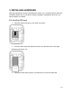
3. INSTALLING HARDWARE SIM card and battery are not pre-installed in the factory; users need to install the SIM card and battery before they use the device. Battery charging is required prior to the first use after the battery is installed. 3.1. Installing SIM card € Open the SIM socket cover as the arrow sign shows. € Place the SIM card on the SIM socket. Make sure the SIM card is in the right direction to fit into the slot. € Restore the SIM socket and press the SIM cover to secure the SIM card.
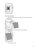
3.2. Installing Battery € Connect the battery connector to the battery socket on the main board as the illustration shown. € Place the battery evenly and properly above the main board. € Restore the bottom cover.
Secure the case by screws and close the USB cap. Make sure that battery is fully charged before you start the operation.
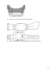
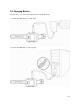
3.3. Charging Battery You may choose one of the following methods to charge the device. 1. Connect the USB adapter to a wall outlet. 2. Connect the USB cable to your computer.
4. CONFIGURING HOLUX TRACKER Holux provides a way (TrackerUser.exe) for end users to configure their tracker. Users can easily modify some of the simple settings for their devices, however if users want to modify some settings which are provided by this utility, please contact you distributor for help. The TrackerUser.exe is the user utility which enables users to fast configure Holux trackers.
/36
4.2. Starting Configuration 1. Open the tool CD and run TrackerUser.exe 2. The following screen appears. 3. Select “Connect”. 4.3. Setting Mobile Phone Numbers € Enter the mobile phone numbers for the tracker to report its position to via short messages. Users can configure four sets (number 1 to 4) of caller mobile phone numbers. Only do the numbers set in the list receive returning message. If the phone number is left blank, the tracker will not return any message to any caller.
Once the configuration is completed, you can click “Set to Device” to save the configuration to your tracker or you can proceed to next section to set the tracking/reporting interval and edit messages.
4.4. Setting Tracking Intervals € € User can set the tracking interval to determine the time interval for the tracker to receive GPS signal. The default tracking interval is “on demand”, which means the tracker will refresh its position only when users turn on GPS to request positioning. There are 3min、10min、30min、1 hour、6 hour、12 hour and 24 hour for selection to set the tracking interval. 4.5. Setting Google key User must set Google key to device for granting map from Google map service.
Once the configuration is completed, you can click “Set to Device” to save the configuration to your tracker. Or you can proceed to next section to edit messages.
4.6. Editing Messages Users can edit 10 outgoing messages and save them in the tracker. Outgoing messages can be sent to the mobile phone preset in the tracker. Outgoing messages will be listed according to their corresponding index numbers at left column. 4.7. Save and Exit Once the configuration is completed, click “Set to Device” to save the configuration to your tracker. Click “Close” to exit this dialogue.
5. BASIC OPERATION 5.1. Parts Names and Functions Part Name Functions USB Use this USB connector to charge the device, or configure the tracker Power/Back Key Press to turn on/off the device; Press to return to the previous page. Menu Key Press to enter the main menu Enter Key Press to confirm a command.
5.2. How to Track The Holux tracker can send its position (latitude and longitude data) to the mobile phones preset in the tracker via SMS (Short Message Service). Mobile phones requesting position get messages and read them to know the position of the device. 5.2.1 Requirements Before you start tracking, make sure: 1. Mobile phone numbers to receive tracking report have been pre-set into the tracker through the user utility TrackerUser.
Those mobile phone numbers preset in the tracker to request the tracker’s position can either acquire position on a regular time interval or by on-demand requests. Tracking by On-Demand Requests If the tracking interval is set to “On demand”, it means the tracker’s position can be acquired by active request from the pre-set mobile phones. The link with the position will be reported. If you do not have any Google Map Key, please contact your dealer.
how to edit messages and save messages to trackers, please refer to the previous section titled “Configuring Holux Tracker” for details. Press the menu key “MENU”. The following screen appears. Press the menu key “MENU” again to select Message. Press Enter to confirm. Press the menu key “MENU” to move down to send message. Press Enter to confirm. The message list appears. Press the menu key “MENU” to move between messages to select. Once the message is selected, press Enter to confirm.
5.5. How to Receive/Read Messages 1. Press the menu key “MENU” twice to enter the main menu for message selection. 2. Press Enter twice to confirm to read messages. 3. Press the menu key “MENU” to select among mobile phone numbers. 4. Press Enter to read the selected message. You can delete the read message by pressing Enter. 5.6. How to Set Time Zone 1. Press the menu key “MENU” three times to enter the main menu for Setting. Press Enter to confirm. 2. Press the menu key “MENU” to add up the value.
6. COMMANDS 6.1 On-Screen Displays This chapter describes all the on-screen displays (OSD) shown on your Tracker 005. Steps to enter each OSD together with respective function will be described in the following sections. 6.1.1 Opening Screen Description: Besides the brand and the product name, the firmware version is displayed on the opening screen. Step: Press POWER for 3 seconds. 6.1.2 Main Screen Icon Description Signal strength of GSM. The level ranges from 0 to 5. SIM card status.
6.1.3 Main Menu Description: Display GPS information, message received/send, and settings menu to set zone and backlight. Step: Press MENU. Icon Function Display GPS information including last fix information for date, time, coordinates, altitude, and speed. Send or read message. Set time zone or turn on backlight. 6.1.4 GPS - GPS Menu Function Description Last Fix Info Select to display the last GPS information including date, time, coordinates, altitudes and speed.
Description: GPS data is acquired: displays the date and time in last positioning. Steps: Press MENU ENTER ENTER Function Key Description Menu Key Return to the previous screen: [Last Fixed Information – Altitude/Speed]. Enter Key Back Key Proceed to the next screen: [Last Fixed Information - Position]. Return to the GPS menu. 6.1.6 GPS - Last Fixed Information - Position No GPS data is acquired GPS data is acquired: displays coordinates in last positioning.
Steps: Press MENU ENTER ENTER ENTER ENTER Function Key Description Menu Key Return to the previous screen: [Last Fixed Information – Position]. Enter Key Proceed to the next screen: [Last Fixed Information – Date/Time]. Back Key Return to the GPS menu. 6.1.8 GPS - GPS Position No GPS data is acquired GPS data is acquired: displays current coordinates; the first row displays latitude and the second row displays longitude.
Back Key Return to the GPS menu. 6.1.10 GPS - Compass No GPS data is acquired GPS data is acquired: Description: displays compass that indicates the current moving direction. The information displayed is only valid when the device is on moving status. Steps: Press MENU ENTER MENU ENTER ENTER ENTER Function Key Description Menu Key Return to the previous screen: [altitude and speed information for GPS]. Enter Key Proceed to the next screen: [satellite signal strength for GPS].
satellites by C/N values order. The numbers in the bottom row represent the satellite ID numbers, the bars in the middle row represent the strength of satellite signals and the higher the bar, the stronger the signal. A hollow bar represents unused satellite, a half-hollow bar shows a satellite is used but the positioning isn't successfully fixed yet and a solid bar means the satellite is being used and the current positioning is successfully fixed.
Menu Key Scroll down and select items. Enter Key Go to selected screen. Back Key Return to the main menu. 6.1.14 Message – Message Information Description: This screen displays the message information including icons for read or not read and the number and date for message sender. Step: Press MENU MENU ENTER ENTER Icon Description Unread message. Read message. Function Key Description Menu Key Scroll down and select items. Enter Key Proceed to next screen [message content].
6.1.16 Message –Confirm Delete Description: This screen is used to confirm the message is deleted. Step: Press MENU MENU ENTER ENTER ENTER ENTER Menu Key Select [No] to give up deleting and Go back to the previous screen: [message content]. Enter Key Select [Yes] to confirm delete. Back Key Go back to the previous screen: [message content]. 6.1.17 Message –Select Message Description: Select the outgoing message content to be sent on this screen.
6.1.19 Message – Select Phone Number Description: Select the default phone number on this screen. Step: Press MENU MENU ENTER MENU ENTER ENTER ENTER Menu Key Scroll down and select items. Enter Key Go to the next screen: [confirm sending message]. Back Key Go back to the previous screen: [select the entire content of the default message content]. 6.1.20 Message –Confirm Sending Description: This screen is used to confirm message is sent.
(The message is sent failed.) Description: This screen displays message send status. Menu Key (no action) Enter Key Select [OK] to go to the message menu. Back Key (no action) 6.1.22 Setting – Setting Menu Description: This screen displays the setting function, currently there are 2 primary functions: time zone and back light. Steps: Press MENU MENU MENU Menu Key Scroll down and select items. Enter Key Go to selected screen. Back Key Go back to the main menu. 6.1.
6.1.24 Setting –Set Back Light Timer Description: This screen is used to configure the time for the backlight to be on. Steps: Press MENU MENU MENU ENTER MENU ENTER Menu Key Change the time for the backlight to be on . Enter Key Save the configuration for the length of time for the backlight and go to next screen [Set Local Time]. Back Key Go back to the setting menu.
Appendix A. FAQ Question Press POWER more than 3 seconds, but can not see power on screen Trouble Shooting 1. 2. contact your distributor. 1. Please charge the device. 2. Place the device to open sky, where GPS signal can be better received. 3. Set the menu to GPS status mode, after device get fixed, it will show correct time and date information, please also check the time offset setting on your device If you still can not get the correct time and date information, please contact your distributor.
Appendix B. TERMINOLOGY EPO Extended Prediction Orbit, predicted ephemeris data MDS Main Data Server, device will send position information to server through HTTP message C/N value Carrier to noise ratio is the ratio of the carrier signal power to the noise power in some specified channel, usually SMS expressed in decibels (dB). Short Message Service TTFF Time to First Fix Windows Mobile Windows-like phone, i.e.
Appendix C. FCC Regulations FCC label can be found in the battery compartment when the battery lid is removed. This device complies with part 15 of the FCC Rules. Operation is subject to the following two conditions: (1) This device may not cause harmful interference, and (2) this device must accept any interference received, including interference that may cause undesired operation.
Appendix D. CE Declaration of Conformity For the following equipment: Tracker-005 GPS Tracking System Is here with confirmed to comply with the requirements set out in the Council Directive on the Approximation of the Laws of the Member States relating to Electromagnetic Compatibility (2004/108/EC), Low‐voltage Directive (2006/95/EC) and the Amendment Directive (93/68/EEC), the procedures given in European Council Directive 99/5/EC and 2004/108/EC. The equipment was passed.