LOADMASTER AXLE SERIES
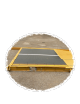
GENERAL This scale system must be installed on a firm and level surface. Particular attention should be paid to the load bearing points at the end of each module. Note that if the area between the ends of the scale is too high it will cause weight errors by rocking the sub-frame. The same condition can be created if surface settling occurs, the center of the frame will not compress the surface at the same rate as the load bearing ends. This will create the same bind as the unleveled surface described above.
4. If dead spaces are to be used these need to be placed as needed. They are designed for either stone fill for temporary use or to be filled with concrete for more permanent use. If filled with concrete a rebar pattern of 12” square of ½” rebar is recommended. If you plan on moving them after concrete is poured a heavy visqueen should be placed below them so they do not adhere to the surface. They also have lifting rings on the four corners if you would like to move them in the future. 5.
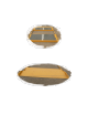
6. Open up the access covers over the load cells. All four corners of the platform and remove the tie down bolts. It is recommended that the tie down bar be laid across the beams of the scale weighbridge. We also recommend that the bolt be placed back into the threaded hole to avoid dirt accumulation. 7. If scale system is installed on a concrete foundation anchors should be installed through the provided anchor holes. One at each load cell access hole. Using a ¾” x 4” concrete anchor. 8.
9. The load cell assembly is designed to rock in place. The cell should be seated in the upper and lower receiver plates. 10. Wiring the load cell are all wired into the junction box located under the access plate in the center of one side of the platform.
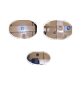
11. If more than one platform is to be wired into an indicator. An option board will be supplied similar to below.
Replacement parts. Upper receiver cup P/n 412-3037-0 one per load cell assembly. Lower receiver cup P/n 412-3038-0 one per load cell assembly. “O” Rings two sizes each receiver cup uses one of each P/n 412-3041-0 1/8” x 1 1/8” x 1 3/8” P/n 412-3040-0 1/8” x 1 7/8” x 2 1/8” Stainless Steel load cell 22.5 metric tons capacity each. Four per scale.