#LT12 - 11/11
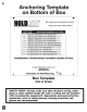
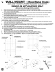
I. Anchoring Template on Bottom of Box • • Drilling guides for CEILING MOUNT Installation Drilling guides for WALL MOUNT installation CONVERTING MAKESHIFT METHODS INTO ENGINEERED SOLUTIONS'" QUICK STANDTM Model# Description SUSPENDED EQUIPMENT PLATFORM 40-SWHP-A CEILING ONLY. NO CROSS BRACES. Suspended Platform supports water heaters up to 20 gallons or 375 pounds. 21-114" x 21-1/4" Pan. 1" PVC DRAIN FITTING. 50-SWHP-A CEILING ONLY. NO CROSS BRACES.
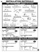
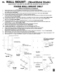
INSTALLATION MATERIALS II. PART DESCRIPTIONS -Included & Not Included (See Below for Quantities) ~Style u,;...,.. ""'"""' for 1-5/8" Strut Channel Screw, Hex Head, #3/8-16 X 1-1/2'' Hot Dipped Galvanized or Zinc Plated Unistrut #P1047 Or Equal.
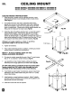
CEILING MOUNT Ill. QUICK STAND™ #40-SWHP, #40-SWHP-A, #40-SWHP-M QUICK STAND™ #50-SWHP, #50-SWHP-A, #50-SWHP-M CEILING MOUNT INSTRUCTIONS 1. Install anchors & hanger rods to overhead structure, using appropriate hardware. (Use template printed on back of box (See Page 2). 2. On models with PVC drain body, assemble plastic fitting, gasket and conduit nut into large drain hole in pan, selecting either the threaded or slip end to be outside the pan for later drain line attachment.
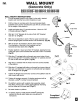
IV. WALL MOUNT (Concrete Only) QUICK STAND™ #40-SWHP-W, #40-SWHP-WM QUICK STAND™ #50-SWHP-W, #50-SWHP-WM WALL MOUNT INSTRUCTIONS 1. Cut-out template printed on box, tape it to the wall in desired location and mark the four anchor locations on wall. 2. Drill four holes in concrete wall to the recommended depth specified by the anchor manufacturer (use 3/8" dia. anchors rated for the weight of this platform). 3. Install and tighten item '0' concrete anchors. Allow min. 5/8" of threads exposed.
WALL MOUNT - (Wood/Metal Studs) v. QUICK STAND™ #40-SWHP-W, #40-SWHP-WM, #50-SWHP-W, #50-SWHP-WM ROUGH-IN APPLICATION ONLY (Where Wood Backing Will Be Installed) 1. 2. Select desired location for wall mount platform (MUST BE 16" CENTER STUD SPACING MAXIMUM). Install 2 X 6 wood backing between studs covering at least two stud bays, in upper and lower locations. Place wood backing at face of wall in contact with drywall. (See Fig #1) 2.1.
VI. WALL MOUNT - (Wood/Metal Studs) QUICK STAND™ #40-SWHP-W, #40-SWHP-WM, #50-SWHP-W, #50-SWHP-WM FINISH WALL MOUNT ONLY (Where No Backing is Installed) 1. 2. 3. 3.1. 4. 4.1. 4.2. 4.3. 5. 5.1. 6. 6.1. 6.2. 7. 8. 9. 10. 11. 12. Select desired location for wall mount platform (STUDS MUST BE 16" CENTER SPACING MAXIMUM). Use template printed on bottom of platform box to mark four attachments points on wall surface; verify that template is held level when making marks.
#LT12 - 11/11