OPERATION & MAINTENANCE GUIDE 2 Channel Digital UHF Transmitter HOLATRON SYSTEMS, LLC 7242 Alliance Court San Diego, Ca. 92119-1522 Phone or FAX: (619) 464-2137 www.holatron.
WARNING Holatron Systems specializes in the design and manufacture of standard and custom electronic control systems where reliability and error free data communication are critical. The transmitter described in this manual is part of a system intended to remotely actuate pyrotechnic or other hazardous devices, and the components of this system have been carefully designed to minimize the possibility of accidental actuation of such devices.
This manual is divided into two sections. The first is a description of the system hardware. The second covers the recommended operating and maintenance procedure. 1.0 HARDWARE DESCRIPTION. The model RFLS-1XT Two Channel Digital UHF Transmitter is a low power two channel, safety locking, hand-held remote control transmitter with a guaranteed range of 60 yards (line of sight operation) when used with the Holatron model RFLS-1RC receiver. A range of 100 yards is typical.
1.2 THE SAFETY LOCKING SWITCH. The Safety Locking Switch is a miniature cylindrical keylock with two positions, “Safe” and “Xmtr Enabled”. In the “Safe” position no RF output occurs even if a button is pressed. In the “Xmtr Enabled” position modulated RF output occurs continuously while a button is pressed. Whether transmitting or not, a red warning indicator near the switch flashes whenever the switch is in its “Enabled” position and the battery voltage is above the low battery detect threshold.
This is a high intensity indicator, visible in direct sunlight, that lights continuously while the transmitter is generating RF output. It is located between the two buttons. It will light even if the battery voltage is below the low battery detect threshold. 1.6 THE BATTERY. Power is supplied from an alkaline 9 volt battery, accessible beneath a slide-out door on the back side of the transmitter. This battery should be replaced when required by conditions described in section 1.3 above.
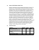
1.8 RADIO INTERFERENCE REDUCTION. Holatron’s design goal is to ensure that data communication errors due to radio interference or to insufficient signal strength due to low battery, exceeding specified range, or conductive objects in the signal path will result in failure of intentional actuation rather than unintended actuation. This goal is achieved by transmitting a 12 bit, 3 state, code repeatedly while a transmitter button is depressed.
2.0 OPERATION AND MAINTENANCE. This section describes the recommended operating procedure and maintenance for the transmitter-receiver system. 2.1 OPERATION. 2.1.1 Connect devices to receiver outputs. With the receiver turned off, set the receiver key switch to its “Enabled” position. Verify continuity through the devices by contacting the tops of the receiver output terminals. 2.1.2 Turn the receiver key switch to its “Shunted position, and turn on the receiver. Verify flashing “Battery OK” light.
2.2 MAINTENANCE. Since there are no calibration or tuning adjustments in the transmitter, the only maintanance required is periodic replacement of the 9 volt battery. This should be done at least once per year, or at the next opportunity if the “Xmtr Enabled” light fails to flash when the transmitter is enabled. If further information or service is required, contact: Holatron Systems, LLC. 7242 Alliance Court San Diego, Ca. 92119-1522 Phone or FAX: (619) 464-2137 www.holatron.