
Data Sheet

UST-20LN Specification
C-42-04072
8/11
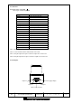
Title
Drawing No
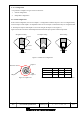
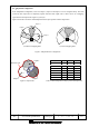
Straight line setting Fan shape setting Ratio setting
Output 1
Output 2
Output 3
UST Sensor
Output 3
Output 2
Output 1
Detection Area
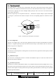
6. Area configuration
It is possible to configure two types of area in the sensor.
1. Normal configuration
2. Independent configuration
6-1 Normal configuration
In the normal configuration, the area for Output 1 is configured first and the shape of it can be configured freely.
Areas for Output 2 and Output 3 are dependent on the set area of Output 1 and therefore they are configured inside
it. The shapes of Output 2 and Output 3 areas can be straight, fan shape or ratio (Figure 3).
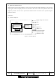
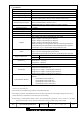
Figure 4 and Table 2 show the relationship between the detected object position and the output states.
Figure 3: Normal area configuration
Figure 4: Output areas Table 2:
Relationship between object position and output states
C
A
B
C
Object position Output 1 Output 2 Output 3
A OFF ON ON
B OFF OFF ON
C OFF OFF OFF