
Data Sheet

UST-20LN Specification
C-42-04072
7/11
Title
Drawing No
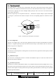
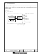
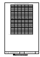
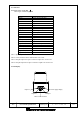
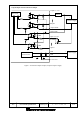
4. Connection
4-1.Power source, I/O Cable
Cable length: 1000mm flying lead
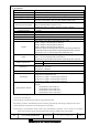
Color Signal
Brown +VIN (DC12V/DC24V)
Blue -VIN
Black Output 1
White Output 2
White (Blue) Output 3
Orange Malfunction Output
Light green Synchronous Output
Gray COM Output -
Red COM Input +
Green Input 1
Yellow Input 2
Purple Input 3
White (Black) Input 4
White (Red) Input 5
Light Blue Synchronous Input
Pink RS422 GND
Yellow (Red) RS422 TXD+
Yellow (Black) RS422 TXD-
Light Blue (Red) RS422 RXD+
Light Blue (Black) RS422 RXD-
Note 1: Input/Output direction is mentioned from the sensor’s side.
Note 2: Colors inside the bracket indicates dual color cable.
Note 3: Keep the input wires open or connect to input Com+ if not in use.
Note 4: Keep the output wires open or connect to output Com- if not in use.
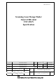
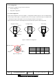
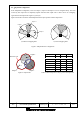
5. LED display
Output 3
Output 2
Micro-USB connector
Output 1
Power supply display