
Data Sheet

UST-10LN Specification
C-42-04211
4/11
Title
Drawing No
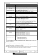
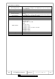
3.Specification
Product name
Scanning Laser Range Finder
Model
UST-10LN
Supply voltage
DC 12V/DC 24V (operation range 10 to 30V, ripple within 10%)
Supply current
150mA (DC 24V) or less (during start up about 450mA is necessary.)
Light source
Laser semiconductor (905nm),
Laser class 1(IEC60825-1:2007 Accession number:1420210-001)
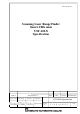
Detection range and object
60mm to 10000mm (white Kent sheet)
60mm to 4000mm (diffuse reflectance 10% )
Minimum detectable size 175mm (changes according to distance)
*1
Accuracy
60mm to 10000mm ±40mm
*2
Standard deviation
σ < 20mm
*2
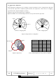
Scan angle
270°
Scan speed
25ms (motor speed 2400rpm)
Angular resolution
0.25°
Start up time
Within 10 sec (start up time differs if malfunction is detected during start up)
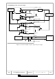
Outputs
Photo-coupler, open collector output Max DC 30V 50mA
Output 1: Output 1 OFF during object detection
Output 2: Output 2 OFF during object detection
Output 3: Output 3 OFF during object detection
Malfunction output: ON during normal operation, OFF during malfunction
Synchronization output: Synchronization signal during Master/Slave operation.
Note: Output 1 to 3 are switched OFF during malfunction state
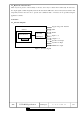
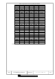
Inputs
Photo-coupler, common anode, power supply is 4mA when input is ON
Input 1 to 5: Area switching inputs (refer Table1)
Synchronization input: Input synchronization signal during Slave operation.
Output response time
*3
OFF
66msec to 3241msec
ON
66msec to 3241msec
Hysteresis
Hysteresis high (Increases 6.25%)
Hysteresis low (Increases 3.125%)
No Hysteresis (Default)
Interface
USB/RS422
LED display
Blue LED: ON during normal operation, blink during the start up,
configuration and malfunction state
Orange LED 1: Output 1 ON during object detection
Orange LED 2: Output 2 ON during object detection
Orange LED 3: Output 3 ON during object detection
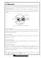
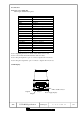
Synchronization function
Synchronization Master/Slave operation mode (can set by using Area
Designer)
*4
Synchronization slave mode (0°)
Synchronization slave mode (90°)
Synchronization slave mode (180°)
Synchronization slave mode (270°)
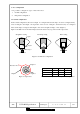
*1
In the case of installing the sensor parallel to the Emitter/Receiver surface. Minimum detectable size of the object
can be set by Area Designer.
*2
Under the factory standard testing condition using white Kent sheet.
*3
Initial setting is 66msec. ON/OFF delay function switching is possible by Area Designer. Response time can be
further delayed by a maximum of 1scan during the area switching.
*4
Initial setting is synchronization master. When using synchronization operation, refer to section 5.3 for details about
synchronization wiring. Synchronization slave setting is possible using Area Designer.