
Data Sheet

UST-10LN Specification
C-42-04211
2/11
Title
Drawing No
1. General
1-1.Operation principle
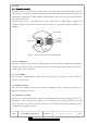
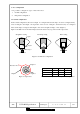
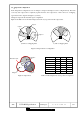
The UST-10LN is a scanning laser range finder. The sensor emits pulsed laser beams within a
270° field of view. When the emitted laser beams are reflected back from an object, its distance is
measured by applying the Time-of-Flight (TOF) principle. The sensor has 1081 measurement
steps with a 0.25° pitch.
The user can preset up to 31 area patterns in the sensor. Each area has 3 outputs; Output 1, Output 2 and
Output 3 (see Figure 1). When the sensor detects an object in the area, corresponding outputs are switched to an
OFF state.
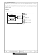
1-2. Area configuration
The user can configure areas in the sensor using application software provided by the manufacturer. Install the
software in a supported operating system and connect the sensor using a USB or RS422 cable. See section 6 for
details on types of area configuration.
1-3.Area switching
The sensor has 5 external inputs for switching the area. Provide the correct signal states on these inputs (see
Table 1) to switch the area.
1-4.Malfunction output
The sensor has a self-diagnostic function. It switches the malfunction output to an OFF state when errors are
detected in the internal components.
1-5.Synchronous operation
The sensor has a scanner synchronization function to avoid mutual interference between multiple sensors. To use
this function connect the Synchronous Output of one sensor (master) to the Synchronous Input of the other
(slave). The slave sensor adjusts its scanner position with a preset time lag from the master. The time lag can be
specified using the application software.
10m
Output 1
270° field
Area pattern
a
UST Sensor
1
a
2
a
3
a
Output 2
Output 3
Figure. 1: Detection area and outputs in UST Sensor