Date: 2016.3.24 Scanning Laser Range Finder Smart-URG mini UST-10LN Specification Symbol Approved by Pages Amended Reason Checked by Drawn by Designed by Date Corrector Amendment No UST-10LN Specification Drawing No.
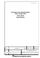
1. General 1-1.Operation principle The UST-10LN is a scanning laser range finder. The sensor emits pulsed laser beams within a 270° field of view. When the emitted laser beams are reflected back from an object, its distance is measured by applying the Time-of-Flight (TOF) principle. The sensor has 1081 measurement steps with a 0.25° pitch. The user can preset up to 31 area patterns in the sensor. Each area has 3 outputs; Output 1, Output 2 and Output 3 (see Figure 1).
1-6.Hysteresis of detection area When objects are present on the boundary of an area, sensor may not detect them continuously. In such cases, the output signals oscillate frequently between the ON and the OFF states. Sensor has hysteresis function that temporarily increases the area size to prevent such oscillation. Ratio of increase can be specified using the application software. 2.
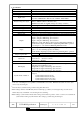
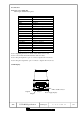
3.Specification Product name Model Supply voltage Supply current Light source Detection range and object Accuracy Standard deviation Scan angle Scan speed Angular resolution Start up time Outputs Inputs Output response time*3 Hysteresis Interface LED display Synchronization function *1 Scanning Laser Range Finder UST-10LN DC 12V/DC 24V (operation range 10 to 30V, ripple within 10%) 150mA (DC 24V) or less (during start up about 450mA is necessary.
3.Specification (Continued) Surrounding intensity Ambient temperature humidity Storage temperature humidity Vibration resistance Shock resistance Insulation resistance Protective structure EMC standards Weight Material Dimensions (W×D×H) Title Less than 15,000lx Note : Avoid direct sunlight or other illumination sources as it may cause sensor malfunction -10°C to +50°C, below 85%RH (without dew, frost) -30°C to +70°C, below 85%RH (without dew, frost) 10 to 55Hz double amplitude of 1.
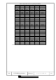
Table 1: Input states and corresponding area number [Input 1] [Input 2] [Input 3] [Input 4] [Input 5] Area Number ON ON ON ON ON Laser off*1 OFF ON ON ON ON Area1 ON OFF ON ON ON Area2 OFF OFF ON ON ON Area3 ON ON OFF ON ON Area4 OFF ON OFF ON ON Area5 ON OFF OFF ON ON Area6 OFF OFF OFF ON ON Area7 ON ON ON OFF ON Area8 OFF ON ON OFF ON Area9 ON OFF ON OFF ON Area10 OFF OFF ON OFF ON Area11 ON ON OFF OFF ON Area12 OFF ON OFF OFF ON Area13 ON OFF OFF OFF ON Area14 OFF OFF OFF OFF ON Area15 ON ON ON ON OFF Ar
4. Connection 4-1.
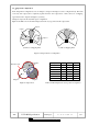
6. Area configuration It is possible to configure two types of area in the sensor. 1. Normal configuration 2. Independent configuration 6-1 Normal configuration In the normal configuration, the area for Output 1 is configured first and the shape of it can be configured freely. Areas for Output 2 and Output 3 are dependent on the set area of Output 1 and therefore they are configured inside it. The shapes of Output 2 and Output 3 areas can be straight, fan shape or ratio (Figure 3).
6-2. Independent configuration In the independent configuration, areas for Output 1, Output 2 and Output 3 can be configured freely. The field covered by each output can be completely separate from the other output areas or there can be an overlapping region between the output areas Figure 5 (a) and (b). ※Output 2 represents the detached region configuration Figure 6 and Table 3 show the relationship between the object position and the output states.
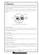
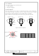
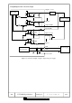
7. Input/Output circuit connection example Output 1,2,3,4,5 Main circuit Resistor + I/O Power supply Output 5 - Output COMInput COM+ 1kΩ Input 1,2,3,4,5 4.7kΩ ON Current 1kΩ 4.7kΩ Input 6 +VIN Power circuit + Power supply -VIN A case is FG. Figure 7: Connection example of inputs, outputs and power supply.
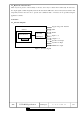
8.The example of synchronous wiring Synchronous Output(master): Light green Synchronous Input(slave): Light Blue Slave Input COM+ 1kΩ Synchronous Input 4.