IFD-E Flame Detector User Manual
Hochiki Europe (UK) Ltd General Description The flame detector is designed for use where open flaming fires may be expected. It responds to the light emitted from flames during combustion. The detector discriminates between flames and other light sources by responding only to particular optical wavelengths and flame flicker frequencies. This enables the detector to avoided false alarms due to such factors as flicking sunlight.
Hochiki Europe (UK) Ltd 3 Application for Flame Detectors Flame detectors are used when detection is required to be: Unaffected by convection currents, draughts or wind Tolerant of fumes, vapours, dust and mist Responsive to a flame more than 25m away Fast reacting The detector is capable of detecting the optical radiation emitted by burning material even noncarbonaceous materials. e.g.
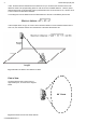
Hochiki Europe (UK) Ltd In fact, the flame detector will detect fires at distances of up to 40 metres, but the flame size at such distances needs to be proportionally greater in order to be sure of reliable detection. Thus the yellow flickering flame that can be detected at 25m, provided that its size is not less than 0.1m², will have to be 0.4m² in order to be detected at 40metres.
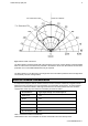
Hochiki Europe (UK) Ltd 5 Fig 3 Detector Field of View Plot The flame detector should be positioned at the perimeter of the room, pointing directly at the anticipated flame or at the centre of the area to be protected. If the detector cannot ‘see’ the whole of the area to be protected, one or more additional detectors may be required. The flame detector is not affected by normal light sources but should be positioned so that sunlight does not fall directly onto the viewing window.
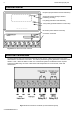
Hochiki Europe (UK) Ltd Detector Interior IR Optics (IR optical flame sensors and filters) Supply ON (Green) (steady if detector functioning correctly) Fire (Red) (indicates a FIRE detected) Test (Yellow) (indicates detector in test mode) DIL Switch (select detector functions) Connection Terminals Fig 4 Detector with Front Cover removed Electrical Connections The flame detector has eight connection terminals as show in Fig 5. Removing the front cover of the flame detector accesses the connections.
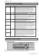
Hochiki Europe (UK) Ltd 7 Connection Terminal Descriptions Terminal No. Mnemonic Function 1 +IN Power Supply +V. +IN is the power supply input to the flame detector and is normally 24Vdc with respect to terminal 2. The current consumption of detector can be monitored to determine the detector status (Fault, Normal, Pre-alarm, Fire). If the detector is in latching mode then this supply line must be broken in order to reset the detector.
Hochiki Europe (UK) Ltd Selectable Functions DIL Switch Settings Relay RL2 Function: 1 2 RL2 off (No fault relay) – For lowest detector current consumption. 0 0 RL2 off, or UV pre-alarm, flame or electrical sparks detected.
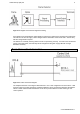
Hochiki Europe (UK) Ltd 9 Fig 7 Block Diagram of the Detector Signal Processing If the detector has interpreted the optical signals as a fire then it produces the required output responses. This will be in the form of supply current changes and the illumination of the red fire LED. The fire relay will also change state if required. The detector is constantly checking itself to ensure it is performing correctly.
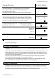
Hochiki Europe (UK) Ltd Detector Supply Current i @ 24Vdc DIL Switch Setting Comment Normal Quiescent Current Alarm (Fire) Current 3mA 9mA 0 0 0 0 4mA 20mA 0 0 1 0 For 4-20mA systems, no relays 8mA 14mA 1 1 0 0 8mA 20mA 1 1 0 1 For 4-20mA systems & relays 8mA 28mA 1 1 1 1 Fire control panels 1 2 3 4 Lowest power configuration, RL1 only Lowest power configuration & relays Table 4 Detector Supply & Alarm Currents If the detector supply current falls below the normal
Hochiki Europe (UK) Ltd 11 The circuit shown above enables the flame detectors to interface with most type of fire alarm control systems. The fire relay RL1 is used to switch the required alarm load ‘R’ to generate a fire alarm signal. An end of line device ‘EOL’ mounted in the last detector provides the system with the ability to monitor the detector fault relay RL2 and the integrity of the interconnecting cables.
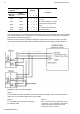
Fig 11 Connection Diagram using a CHQ-DIM Dual Input Module (or CHQ-S) 2-3-0-808/ISS3/OCT11 Hochiki Europe (UK) Ltd
Hochiki Europe (UK) Ltd 13 Fig 12 Connection Diagram using a CHQ-POM Powered Output Module NOTE: The CHQ-POM has a variable output, this should be set at 30mA.
Fig 13 Connection Diagram using a CHQ-DZM Dual Zone Monitor (or CHQ-Z) 2-3-0-808/ISS3/OCT11 Hochiki Europe (UK) Ltd
Hochiki Europe (UK) Ltd 15 Installation It is important that the detectors are installed in such a way that all terminals and connections are protected to at least IP20 with the detector cover fitted. The earth bonding terminals are provided for convenience where continuity of a cable sheath or similar if required. Adjustable mounting brackets and weather shields are available as shown below in Figs 14 and 15.
Hochiki Europe (UK) Ltd Service & Repairs Servicing of the fire protection system should be carried out by competent persons familiar with this type of system, or as recommended by the local regulations in force. Only the manufacturer or equivalent authorised body may carry out repairs to the flame detectors. In practical terms this means that flame detector may be repaired only at the manufacturer’s factory.