
User Manual

FireNET FNP-LED I & O Manual v1.0 UL
9
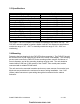
3.3 Specifications
Description Specification
Supply Voltage 21 – 30 VDC
Maximum Input Rating 24 VDC @ 360mA
Standby Current
Red LED Driver Board Contains 8 LEDs = 13mA
Red LED Expansion Board Contains 16 LEDs = 13mA
Green LED Expansion Board Contains 16 LEDs = 13mA
Yellow LED Expansion Board Contains 16 LEDs = 13mA
Alarm Current
Red LED Driver Board Contains 8 LEDs = 45mA
Red LED Expansion Board Contains 16 LEDs = 45mA
Green LED Expansion Board Contains 16 LEDs = 45mA
Yellow LED Expansion Board Contains 16 LEDs = 45mA
Terminal Capacity 14 – 24 AWG solid or stranded wire
Communications Interface RS485 serial bus protocol
The FireNET FNP-LED Graphic LED Display is intended for dry indoor use only. The
FNP-LED must be installed in locations where it will NOT be exposed to temperatures
outside the range of 32° - 120°F or humidity outside the range of 10% - 93% non-
condensing.
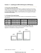
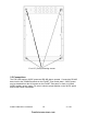
3.4 Mounting
Determine the best location for the FNP-LED before mounting it. The FNP-LED should
be mounted on a dry flat surface at eye level to the center of the display. The mounting
screws used to secure the FNP-LED to the mounting surface must be a minimum of
5mm in diameter, and all four mounting locations must be used. The unit should be
located within 3,900 feet (1,200 meters) of the FireNET Plus control panel, and be
connected with a suitable RS-485 cable.
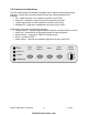
The unit must not be mounted in another enclosure or near sources of excessive heat.
Knockouts are provided on the enclosure for ease of wiring installation. Use 13/16”
(20mm) cable connectors to pass wiring through the knockouts into the cabinet
enclosure.
firealarmresources.com