
User Manual

FireNET FNP-LED I & O Manual v1.0 UL
13
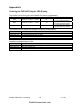
3.7 Programming
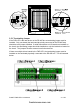
The Graphic LED Display consists of an 8-way LED board; this board also contains the
common LEDs and controls if they are used. Additional 16-way LED boards may be
added, up to a maximum of 32 boards
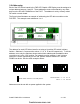
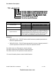
The LED boards are set by default to operate on a fire alarm condition. The outputs of
the 8-way LED board are assigned to zones 1 – 8 respectively. If a 16-way LED board
is added its outputs are assigned to zones 9 – 24 respectively. If additional LED boards
are added their outputs will also be set to zones 9 – 24, and may need to be
reprogrammed to suit the installation.
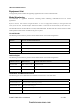
3.8 Adding or Changing LED Positions
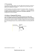
The construction of the FNP-LED Graphic Display is such that it is simple to add,
remove or change the position of LED indicators without the need for special tools or
wiring. The indicators are installed on a steel plate which has holes on a ¼” (6mm) grid.
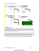
This steel plate is covered by a printed building plan which reveals only the areas of the
plate where the indicators are located. If changes or additions are made to the building
plan, a new building plan layout can be produced and installed on an existing FNP-LED
panel.
firealarmresources.com