
User Manual

FireNET FNP-LED I & O Manual v1.0 UL
12
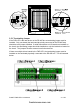
3.6 Addressing
Each of the LED driver boards in the FNP-LED Graphic LED Display must be assigned a
unique address between 1 and 32. These addresses must not be shared by any other
device on the RS-485 COMMS bus of the FACP. The address is set by a binary coded
DIP switch on each board.
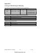
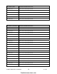
The figure below illustrates an example of addressing the LED driver modules on the
FNP-LED. This example uses addresses 1 to 4.
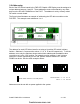
8 LED Board
1 to 8
Address 1
16 LED Board
9 to 24
Address 2
16 LED Board
25 to 40
Address 3
16 LED Board
41 to 56
Address 4
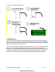
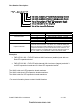
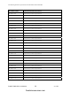
The address for each LED driver board is set using a 6-position DIP-switch in binary
fashion. Switches 1-6 represent the values 1, 2, 4, 8, 16 and 32 respectively. To set the
address, move only the switches whose values when added equal the address value
you wish to set, to the “ON” position. For example moving switches 1 and 3 (whose
values are 1 and 4 respectively) to the “ON” position sets the address of 5 into the
RS485 bus device. See the other examples below:
Addresses must be set with no power applied to the system.
ADDRESS 6 ADDRESS 13 ADDRESS 21
Shows switch actuator in the ON position.
Switch Number – 1 2 3 4 5 6
Value – 1 2 4 8 16 32
1
11
firealarmresources.com