FireNET Plus FNP-LED Graphix LED Display Installation and Operation Manual Hochiki America Corporation 7051 Village Drive, Suite 100 Buena Park, CA 90621-2268 714.522.2246 Corporate Headquarters 800.845.6692 Technical Support http://www.hochiki.com firealarmresources.com Version 1.
Table of Contents Table of Contents ........................................................................................................................... 2 Section 1 – Introduction ......................................................................................................................................................... 3 1.1 Limitations of Fire Alarm Systems ........................................................................ 3 Section 2 – General Wiring Specifications ...........
Section 1 – Introduction The FireNET FNP-LED Graphic LED Display provides a flexible and expandable solution for graphical LED display panels via a simple four-wire data link connected to the FireNET Plus control panel (FW version must be V07.0000 or higher). 1.
Alarms Cannot Guarantee Warning or Protection: Fire alarm system cannot guarantee warning or protection against fire in every potential situation. A study by the Federal Emergency Management Agency (an agency of the United States government) indicated that smoke detectors may not go off or give early warning in as many as 35% of all fires. Limitation on Fire Alarm Effectiveness: A fire alarm system may not provide timely or adequate warning, or simply may not function, for a variety of reasons.
x Unheeded Warning: Warning devices (including horns, sirens, and bells) may not alert people or wake up sleepers who are located on the other side of closed or partially open doors. A warning device that activates on a different floor or level of a dwelling or structure is less likely to awaken or alert people. Even persons who are aware may not notice the warning if the alarm is muffled by noise from a stereo, radio, air conditioner or other appliance, or by passing traffic.
Section 2 – General Wiring Specifications Care should be taken when wiring the system to avoid situations that would contribute to inducing electrical noise from one wire to another. Induced noise can interfere with telephone communications or cause erratic system operation. Follow these general guidelines to plan your system wiring prior to installation. x Route high and low voltage wiring separately. Maintain a minimum 2” separation between high and low voltage wiring throughout the building.
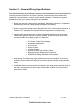
Section 3 – Installing the FNP-LED Graphic LED Display 3.1 Overview of the FNP-LED The FireNET FNP-LED Graphic LED Display is a graphical annunciator that provides a flexible solution for fire alarm systems. The FNP-LED allows LED positions to be added or removed without wiring changes. The modular nature of the FNP-LED supports up to 88 standard LED indicators. Please contact Hochiki America for applications requiring more than 88 LED indicators. 3.1.
3.2 Controls and Indications The FNP-LED Graphic LED Display is available with or without controls and common indicators.
3.
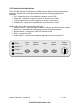
Four 1/5" (5 mm) mounting screws 3.5 Connections The FNP-LED requires 24VDC power and RS-485 data to operate. Connect the RS-485 data circuit to the COMMS terminals on the FireNET Plus control panel. 24VDC power may be obtained from the AUX power on the FireNET Plus panel, or from a UL listed 24VDC auxiliary power supply. Be sure to observe proper polarity on the 24VDC power and RS-485 circuit connections. FireNET FNP-LED I & O Manual 10 firealarmresources.com v1.
24V 0V COMM - COMM + 3.5.1 Terminating Jumper If the FNP-LED is the last device on the RS-485 bus a terminating jumper must be installed. Only one board (the last board physically connected to the RS-485 bus) should have the jumper installed. If serial annunciators or I/O boards are installed on the circuit, the terminating jumper should be installed on only the last device located on the circuit. The jumpers must be removed on all other devices.
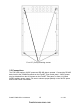
3.6 Addressing Each of the LED driver boards in the FNP-LED Graphic LED Display must be assigned a unique address between 1 and 32. These addresses must not be shared by any other device on the RS-485 COMMS bus of the FACP. The address is set by a binary coded DIP switch on each board. The figure below illustrates an example of addressing the LED driver modules on the FNP-LED. This example uses addresses 1 to 4.
3.7 Programming The Graphic LED Display consists of an 8-way LED board; this board also contains the common LEDs and controls if they are used. Additional 16-way LED boards may be added, up to a maximum of 32 boards The LED boards are set by default to operate on a fire alarm condition. The outputs of the 8-way LED board are assigned to zones 1 – 8 respectively. If a 16-way LED board is added its outputs are assigned to zones 9 – 24 respectively.
To add or change an LED indicator: 3.9 Maintenance The FNP-LED requires little or no maintenance other than to ensure that the fascia is clean and clear of obstructions. If required, the fascia can be wiped with a barely damp cloth. Cleaning solutions other than those specifically designed for plastics such as anti static spray cleaners should not be used.
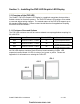
Appendix A Ordering the FNP-LED Graphic LED Display The following enclosure styles are available for various configurations: Enclosure Dimensions Max # of LEDs Max # of boards AM-2 14.50”W x 12.25”H x 3.50”D 24 AM-3 14.50”W x 18.90”H x 4.25”D 56 AM-4 14.50”W x 24.25”H x 4.
Part Number Description: Options Option Type Valid Selections Description 0 AM2 14.50”W x 12.25”H x 3.50”D 2 AM3 14.50”W x 18.90”H x 4.25”D 3 AM4 14.50”W x 24.25”H x 4.25”D 1 Red 2 Charcoal The number of expansion boards that can be installed is dependent on the size of the enclosure. The three “YYY” locations identify the amount of expansion boards installed in the enclosure. The amount of expansion boards may not exceed the size of the enclosure.
FNPͲLED Installation Manual Equipment List This appendix provides models and supporting equipment for all versions of the FNP-LED. Model Numbering The FNP-LED is a graphical annunciator containing model numbering, FNP-LED-XX-YYY for custom applications.
FNP-LED Models The following models are provided for the FNP-LED-AM2 cabinet of the FNP-LED: AM2 CABINET, RED EXPANSION BOARD POPULATION FNP-LED-01-000 0 red, 0 green, 0 yellow expansion board FNP-LED-01-001 0 red, 0 green, 1 yellow expansion board FNP-LED-01-010 0 red, 1 green, 0 yellow expansion board FNP-LED-01-100 1 red, 0 green, 0 yellow expansion board AM2 CABINET, CHARCOAL EXPANSION BOARD POPULATION FNP-LED-02-000 0 red, 0 green, 0 yellow expansion board FNP-LED-02-001 0 red, 0 green,
AM3 CABINET, RED EXPANSION BOARD POPULATION FNP-LED-21-102 1 Red, 0 Green, 2 Yellow Expansion Board FNP-LED-21-111 1 Red, 1 Green, 1 Yellow Expansion Board FNP-LED-21-120 1 Red, 2 Green, 0 Yellow Expansion Board FNP-LED-21-201 2 Red, 0 Green, 1 Yellow Expansion Board FNP-LED-21-210 2 Red, 1 Green, 0 Yellow Expansion Board FNP-LED-21-300 3 Red, 0 Green, 0 Yellow Expansion Board AM3 CABINET, CHARCOAL EXPANSION BOARD POPULATION FNP-LED-22-000 0 Red, 0 Green, 0 Yellow Expansion Board FNP-LED-2
The following models are provided for the AM4 cabinet of the FNP-LED: AM4 CABINET, RED EXPANSION BOARD POPULATION FNP-LED-31-000 0 Red, 0 Green, 0 Yellow Expansion Board FNP-LED-31-001 0 Red, 0 Green, 1 Yellow Expansion Board FNP-LED-31-010 0 Red, 1 Green, 0 Yellow Expansion Board FNP-LED-31-100 1 Red, 0 Green, 0 Yellow Expansion Board FNP-LED-31-002 0 Red, 0 Green, 2 Yellow Expansion Board FNP-LED-31-011 0 Red, 1 Green, 1 Yellow Expansion Board FNP-LED-31-020 0 Red, 2 Green, 0 Yellow Expans
AM4 CABINET, RED EXPANSION BOARD POPULATION FNP-LED-31-121 1 Red, 2 Green, 1 Yellow Expansion Board FNP-LED-31-130 1 Red, 3 Green, 0 Yellow Expansion Board FNP-LED-31-202 2 Red, 0 Green, 2 Yellow Expansion Board FNP-LED-31-211 2 Red, 1 Green, 1 Yellow Expansion Board FNP-LED-31-220 2 Red, 2 Green, 0 Yellow Expansion Board FNP-LED-31-301 3 Red, 0 Green, 1 Yellow Expansion Board FNP-LED-31-310 3 Red, 1 Green, 0 Yellow Expansion Board FNP-LED-31-400 4 Red, 0 Green, 0 Yellow Expansion Board FN
FNP-LED-31-500 5 Red, 0 Green, 0 Yellow Expansion Board AM4 CABINET, CHARCOAL EXPANSION BOARD POPULATION FNP-LED-32-000 0 Red, 0 Green, 0 Yellow Expansion Board FNP-LED-32-001 0 Red, 0 Green, 1 Yellow Expansion Board FNP-LED-32-010 0 Red, 1 Green, 0 Yellow Expansion Board FNP-LED-32-100 1 Red, 0 Green, 0 Yellow Expansion Board FNP-LED-32-002 0 Red, 0 Green, 2 Yellow Expansion Board FNP-LED-32-011 0 Red, 1 Green, 1 Yellow Expansion Board FNP-LED-32-020 0 Red, 2 Green, 0 Yellow Expansion Boar
AM4 CABINET, CHARCOAL EXPANSION BOARD POPULATION FNP-LED-32-103 1 Red, 0 Green, 3 Yellow Expansion Board FNP-LED-32-112 1 Red, 1 Green, 2 Yellow Expansion Board FNP-LED-32-121 1 Red, 2 Green, 1 Yellow Expansion Board FNP-LED-32-130 1 Red, 3 Green, 0 Yellow Expansion Board FNP-LED-32-202 2 Red, 0 Green, 2 Yellow Expansion Board FNP-LED-32-211 2 Red, 1 Green, 1 Yellow Expansion Board FNP-LED-32-220 2 Red, 2 Green, 0 Yellow Expansion Board FNP-LED-32-301 3 Red, 0 Green, 1 Yellow Expansion Boar
AM4 CABINET, CHARCOAL EXPANSION BOARD POPULATION FNP-LED-32-401 4 Red, 0 Green, 1 Yellow Expansion Board FNP-LED-32-410 4 Red, 1 Green, 0 Yellow Expansion Board FNP-LED-32-500 5 Red, 0 Green, 0 Yellow Expansion Board Part Number Assignment Matrix The following part number matrix describes the component structure of the FNP-LED: Part Number Assignment Matrix For The FNP-LED Graphic Annunciator FNP-LED-XX-YYY This is the number of 'YELLOW' LED expansion boards This is the number of 'GREEN' LED expan
WARRANTY Hochiki America Corporation manufactured equipment is guaranteed to be free from defects in materials and workmanship for a period of one (1) year from date of original shipment. HOCHIKI will repair or replace, at its option, any equipment which it determines to contain defective material or workmanship. Said equipment must be shipped to HOCHIKI prepaid. Return equipment will be prepaid by HOCHIKI.