
User Manual


Page 30 of 40 FIREli nk - 25 – Installation Manual
© 2010 Hochi ki E ur ope ( UK) Ltd
9-5-0-344/ISS4/OCT10
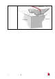
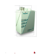
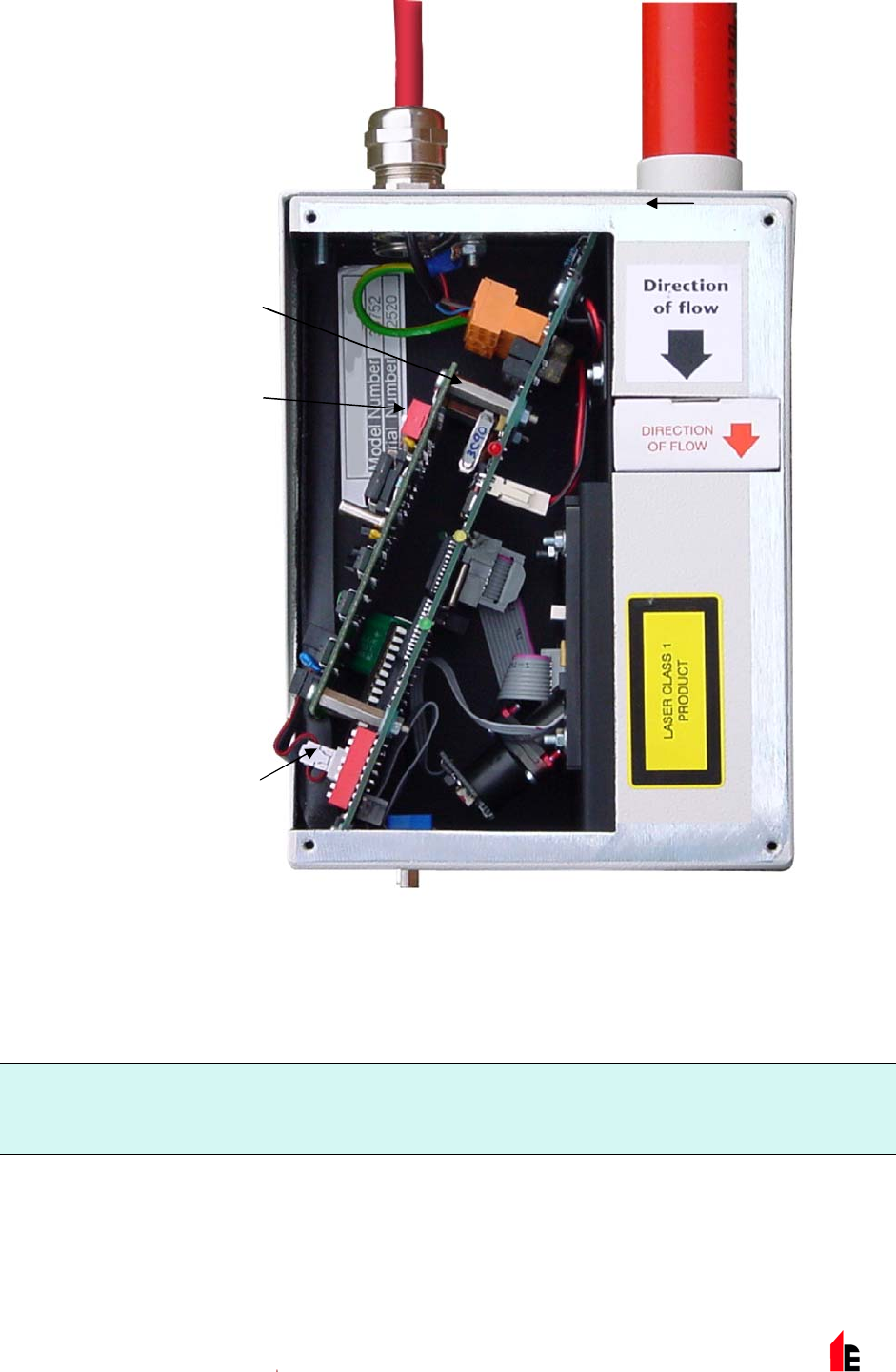
FIRE link-APIC
Mount ing Studs
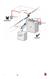
FIRE link-APIC
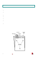
Addres s Swit c hes
(x 2)
FIRE link-APIC
Interface
Connection
The c onnec tions to the Fire P anel are made using t he BUS L1 and H1 (bus 1 i nput and out put) and the
BUS L2 and H2 ( bus 1 i nput and out put) terminal connec tors shown in Section 4.1. 4.
The only setti ngs that need to be m ade ar e on the FIREli nk - A PIC addr ess DIP s witches. The star t loop
address Is enter ed on SW1 and the end loop addr es s on SW 2. In the case of a single FIREli nk - 25 the
start and end addr es se s will be the same.
NOTE: The det ec tor address on the SenseNET loop and the Fire Panel addr essable protocol addr ess are
the same, in other words, no addre ss translation i s performed. Some protocols may not support
all the available alarm l ev els and fault reporti ng is usually a general f ault wit h no detai led fault
informati on. Please consult the specific FIREli nk -APIC documentati on for m or e information.