
User Manual


Page 28 of 40 FIREli nk - 25 – Installation Manual
© 2010 Hochi ki E ur ope ( UK) Ltd
9-5-0-344/ISS4/OCT10
5 Interfacing
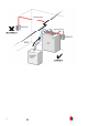
Because of the fl exi ble nature of the FIRElink-25 detector and t he many possible configurations, there ar e
m any opt ions for interfaci ng the detectors to the Fire Panel. These incl ude m any third party int erf ac es
av ailable from vari ous manufacturer s. B ec ause of this, it is not possible to give a complete li st of all
interfaci ng m ethods but t he followi ng pages will giv e details of the most c ommon methods that ar e lik ely
to be used.
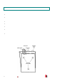
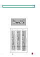
5.1 S etti ng the Detector Address
In or der to identify itself to the PC Command Modul e or fir e panel, each detec tor needs to have a unique
address ranging f r om 1 t o 127. The detector addr ess is simply set on the red DIP switch SW 1 at the top
left of the opened detec tor on the main circ uit board. The swi tch settings are on for 1 and off for 0, and
the detector addr ess is set as a 7-bit binary code ( switc h 8 equates to a v alue of 128 and so is outside t he
usable address range). A n example is shown below.
The addr es s equates to 01100011 i n binary, or (1 x 1) + (1 x 2) + (0 x 4) + (0 x 8) + (0 x 16) + (1 x 32) +
(1 x 64) + (0 x 128) = 99.
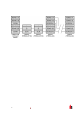
The full range of av ail able addresses and their rel evant swit ch settings are shown below: