
User Manual


Page 26 of 40 FIREli nk - 25 – Installation Manual
© 2010 Hochi ki E ur ope ( UK) Ltd
9-5-0-344/ISS4/OCT10
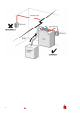
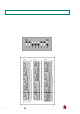
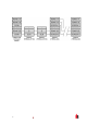
The following il lustration shows the power and si gnal connections to t he doc king station for connect ion to
a single SenseNET cable:
Power Suppl y S c r een Wire to Earth Stud
SenseNET/RS485
Bus A W ire
SenseNET/RS485
Bus B W ire
Power Suppl y
0V Wire
SenseNET/RS485
Bus Screen Wire
Wire from "Earth" Terminal to Earth Stud Power Suppl y +24V Wire
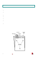
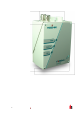
4.2 Final installation
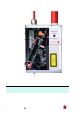
Onc e the power and si gnal connections are made slide the detec tor body up into the docking station and
fasten i t into position usi ng the M4 pan head scr ews provided. Slot the power and signal terminal blocks
into the r elevant sockets on the det ec tor PCB (t hey will only cli c k fully home in the correc t orientation) and
replace the det ector c ov er using the four M3 pan head screws provi ded.
NOTE: The det ec tor is designed solely for operation with the f r ont c ov er securely f itted using all four fixi ng
screws.
Rem oving the detector is sim ply the r everse of this process, leaving the pipe-work and wiring connect ions
inst alled in the docki ng st ation.