
User Manual


FIREli nk - 25 – Installation Manual Page 25 of 40
© 2010 Hochi ki E ur ope ( UK) Ltd
9-5-0-344/ISS4/OCT10
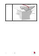
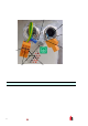
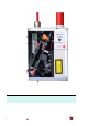
Pi ped Exhaust Docking Station
4.1.1 Mechanical Installation
The doc k ing station is connected to the i nstalled sampling pipe-work and fixed to the wall or mount ing
surface using 3 off screws of a ty pe appr opri ate to the mounting surface. E nsure that the sampling and/or
ex haust pipes are securely seated in the pipe ports befor e fixi ng. If using a pi ped ex haust doc k ing station
be sure that the sampling and exhaust pipes are f itted into the r elev ant ports as shown i n sect ion 4.1.
4.1.2 Electrical Installation
The FI RE link-25 detect or is supplied wi th removable terminal blocks (See illustrations in Section 0).
These are simply rem oved from t heir sockets by lifting them up at right angles to the c ircuit board. Take
note of the orientation of each terminal block and its function befor e removing it. It may al so be beneficial
to m ar k the c onnec tion wires wi th suitable i dentif ication labels or coloured rings to aid in the connecti on
proces s.
NOTE: All c onnec tions should be m ade with the power t ur ned off.
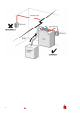
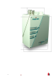
4.1.3 Power Supply Connections
The power supply cabl e should be of screened type and should be led through t he metal c able gland
provided, leaving about 35mm of the c able extendi ng from the bott om of t he c able gl and. Depending on
the type of c able used, i t may be necessary to increase the diameter of the cable with sl eev ing or
insulati ng tape t o ensure t hat the c able is firmly hel d when the c able gl and is fully tight ened.
Rem ove the detect or cov er by unfastening the four screws at the front of the unit and detach the power
supply terminal bloc k . T his i s at the top l eft with the detector held with the serial port at the bottom of t he
unit.
NOTE: B e aware of the ori entati on of the terminal block.
Connect 0V and +24VDC to the “0V” and “ 24V ” screw terminals respectively. Connect the screen wire to
the ear th stud on the docking stati on and c onnec t a second wire from t he “Earth” terminal t o the doc ki ng
station earth stud. The pic ture i n S ection 4.1 shows the location of the earth stud. Fix the earth wi r es i n
place with the nuts prov ided.
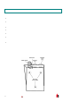
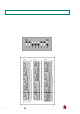
4.1.4 Signal Connections
To c onnec t the signal wir e, lead a suitable wir e type (RS485
cable 9841, 120 ohm screened t wist ed pair or equivalent)
thr ough the second cable gland and tighten it into posi tion with
about 35m m of cable fr om the bot tom of the c able gland.
Rem ov e ei ther the three-way termi nal block next to the power
supply socket if connecting the det ector to a S enseNET
system , or the four-way “Bus” terminal bloc k if connect ing the
detector to an alarm panel in conj unction with the FIREli nk -
APIC addressable program mabl e interface card (see section
5.3) .
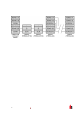
For ex am ple, in a SenseNET system using screened c able
connect the screen wire(s) to the “SCN” terminal , B us A wire( s)
to the “A” termi nal and Bus B wire(s) to the “B” termi nal. If the
detec tor i s i n the middle of a SenseNET c hain, with input and
output connections, it may be more convenient to link the
common Bus A, Bus B and screen wires to single A, B and
screen wir es for linking to the terminal block.
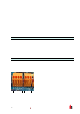
FIRE link-APIC
Address
Terminals
RS485/Sens eNET
Terminals