
User Manual


FIREli nk - 25 – Installation Manual Page 21 of 40
© 2010 Hochi ki E ur ope ( UK) Ltd
9-5-0-344/ISS4/OCT10
B
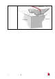
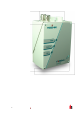
Above Ceilin g
S a mplin g wi t h
detector
mounted in
c eiling vo id.
3.1 System Design
Simpl e desi gns with short sampling pipes produce the best result s. Complex sampling pipe runs should
be av oided wi th the FIRElink - 25 detector. The use of ‘T’ branch-pipes is not recommended. To assist in
design and t o verify system performance, it is advisable to use the FIRElink PipeCAD® sampling pipe
m odel ling software.
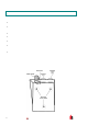
Al ways loc ate the sampling points in positions to whi c h smoke m ay reasonably be expected to travel. Do
not expect ceiling m ounted sampling points to oper ate satisfact oril y if air flow fr om air - c onditioning
system s keeps the cool smoke from an inci pient fire reaching from reachi ng ceili ng level. In this instance
it is usually bet ter to loc ate the sampling pipe directly i n the airf low (f or ex am ple ac ross the ret ur n air
register of an air conditioning unit ).
Ther e is no substitute for carr yi ng out sm ok e tests prior to installation of pipe work to indicate sui table
sampling point location.
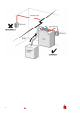
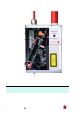
No m ore than ONE Air Handling Unit may be protec ted wi th one FIREli nk - 25 detector. In thi s appli c ation,
ensure that the sampling pipe is raised clear of high v eloc ity ai r in the immediate vicinity of the air intake
grille on stand- off posts as shown below: