
User Manual


Page 14 of 40 FIREli nk - 25 – Installation Manual
© 2010 Hochi ki E ur ope ( UK) Ltd
9-5-0-344/ISS4/OCT10
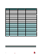
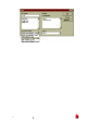
2.7 Flow Monitoring Tab
2.7.1 Flow Rate
This functi on i s for displ ay pur poses only, and shows a value c or respondi ng to the current airflow thr ough
the detector.
2.7.2 Flow High Limit
This value is the level above which airflow needs to i ncrease to trigger a fault indicati on (which may
indicate a loose or dam aged inlet pipe). Fl ow low limi t and Flow high limi t parameters are autom aticall y
set up on i nitial power - up.
2.7. 3 Flow Low Lim i t
This value is t he lev el below whic h airfl ow needs to be reduced t o trigger a f ault reading (which m ay
indicate a blocked pipe). Flow l ow lim it and Flow high limit parameters are automatically set up on initi al
power-up
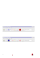
2.7.4 Flow Fault Delay
This featur e requi res the Rem ote Control Soft ware ver si on 3.2 or later, available from the Hochiki E ur ope
Tec hnical Support Department (psupport@hochik ieurope.com) .
The default flow fault t hr eshol ds on t he FI REl ink-25 are set to m eet t he stri ngent airflow m onitoring
requirements of E N54- 20, with a default flow faul t delay of 30 seconds. This may lead to unwanted flow
faul ts bei ng gener ated when local conditions cause short - term variati ons i n airflow. To help alleviate such
issues, the flow fault delay is programmable from 30 to 240 seconds. The flow lev el needs to be above
the high flow thr eshol d or below the l ow flow threshold throughout the delay period for a fault t o be
generated.
NOTE: When setting the value of this function, it is important to take into account that the control unit (for
ex ample, fire panel) may not react imm ediately to a trouble si gnal being generat ed by the
detec tor, and thi s will add to the total fault response tim e of the system.
The function value m ust be chosen so that the total time bet ween the det ec tor enter ing a fault condi tion
and a fault si gnal bei ng gener ated by the panel m eets the requir em ents of local or national fire
regulati ons. The maximum allowable response time for EN54-20 compliance is 300 seconds, and t hat for
NFPA 72 c om pliance is 200 seconds.
As an ex am ple: in the latter case, if the flow faul t delay were set t o 180 seconds (within the limit), but t he
fire panel did not gener ate a fault indication for another 25 sec onds, the total response time of 205
seconds means the system would not c om ply with the regul ations.
If documented figures are unava ilable for the fire panel reaction time, co mpliance w ith reaction time
regulati ons may only be ver ified by post-installation testing.
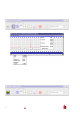
2.8 Miscellaneous Tab
2.8.1 Access Code
This is the access c ode required to amend progr ammable parameters. The defaul t c ode is 0102. Once
the appr opr iate code is enter ed it may be c hanged here to any four digit num ber to limit unauthor ised
access.