esp FIREbeam INSTALLATION MANUAL
This manual details the installation of: ESP FIREbeam Reflective Optical Beam Smoke Detector If you have any queries regarding these products or their functionality please contact: Hochiki Europe (UK) Limited Grosvenor Road Gillingham Business Park Gillingham Kent ME8 0SA Tel: +44 (0) 1634 260133 Fax: +44 (0) 1634 260132 Web: http://www.hochikieurope.com Email: psupport@hochikieurope.com 2011 Hochiki Europe (UK) Ltd. All rights reserved.
ESP FIREbeam – Installation Manual Page 3 of 19 Table of Contents 1 Distance and Position Guidelines ..................................................................................................................... 4 1.1 Distance ...................................................................................................................................................... 4 1.1.1 5 to 40 metres - The Standard ESP FIREbeam .........................................................................
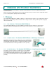
Page 4 of 19 1 ESP FIREbeam – Installation Manual Distance and Position Guidelines These guidelines are recommendations only and it is important that you refer to your appropriate governing standards at all times. When positioning your ESP FIREbeam there are important factors that you should consider, mainly what distance you are covering and the optimal position in the building. 1.1 Distance The standard ESP FIREbeam is suitable for distances of 5m to 40m to the reflector.
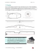
ESP FIREbeam – Installation Manual Page 5 of 19 1.2 Position A roof is considered flat unless the height of the apex is greater then 0.6m. If the roof is flat the ESP FIREbeam system can be placed anywhere under the roof between 0.3m and 0.6m below the roof, up to a maximum height of 40m from the floor. The ESP FIREbeam has a detection area of 7.5m either side of the beam. If the roof is considered to have an apex, place the ESP FIREbeam system 0.3m to 0.
Page 6 of 19 2 ESP FIREbeam – Installation Manual Installing, Commissioning and Testing 2.1 Step 1 - Mounting the Head Screw the head backing plate to the wall - always try to use as sturdy a location as possible, such as brick or major structural steels (avoid mounting to outer metal cladding etc). Avoid mounting the head where direct sunlight can shine directly into the ‘eyes’ of the beam (care should be taken when mounting in glass atriums). Ambient sunlight will not affect the beam.
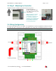
ESP FIREbeam – Installation Manual Page 7 of 19 2.3 Step 3 - Mounting the Controller Important mount the controller at eye level and ensure easy access. Screw in through holes provided outside of the rubber seal. Wire to head using colour coded terminals. If this connection is not made ERROR will appear on the controller, this connection can be checked by reading the resistance across the black and grey terminals, they will read 110 ohm if OK or 220 ohm if not connected properly. 2.
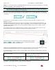
Page 8 of 19 ESP FIREbeam – Installation Manual 2.5 Step 4 - Commissioning Commissioning the ESP FIREbeam is a simple procedure outlined in the following step by step explanation. 2.5.1 Stage One - Language and Commissioning Speed IMPORTANT. Do NOT put the reflector up or COVER it if already in place. Power up the unit and you will see the screen will then default to or Access the menu by pressing the enter button The first screen you see is English.
ESP FIREbeam – Installation Manual Page 9 of 19 Receiver sensitivity starts off at 5% and output power starts at 10%. The beam will start by raising its sensitivity first and can rise all the way up to 100%, after this the output power will rise. The objective of pre-alignment is to adjust the output power to the correct levels for the distance to be covered. As there is no reflector we are looking for a reflection off the far wall.
Page 10 of 19 ESP FIREbeam – Installation Manual NOW place or uncover the reflector on the blank wall directly opposite the beam head ensuring there is a clear path through any obstructions such as structural steels etc. NOTE: It is important that there is a clear line of sight between the reflector and beam head. The beam must see at least 200mm of clear space around the reflector to enable the beam to see the edges of the reflector to allow successful auto alignment in the following stage.
ESP FIREbeam – Installation Manual 2.5.4 Page 11 of 19 Stage Four - Auto-Alignment Having received an AQ reading of over 40% in manual mode press enter to exit manual and enter again to go into auto alignment mode. First you will see the sensitivity and power readings drop if the received signal is over 100%. Once at 100% or if the reading is under 100% the ESP FIREbeam will automatically move its y and x axis until it centres itself onto the middle of the reflector.
Page 12 of 19 3 ESP FIREbeam – Installation Manual Screen and Menu Systems 3.1 Home Screen NORMAL This is the screen you would normally see when the beam is commissioned. FIRE The air quality level has fallen below the fire threshold setting. If alarm is set to latching and you need to reset from fire press enter to see this screen and press enter again to reset and return to the normal screen. This can also be reset by dropping the power to the beam for 5 seconds.
ESP FIREbeam – Installation Manual Page 13 of 19 3.
Page 14 of 19 ESP FIREbeam – Installation Manual 3.3 Individual Menu Items 3.3.1 Language The language is factory set to English as default. If this is okay press enter to continue to commissioning or up to return to the home screen. To change the language use the right and left keys to change to your preferred language and press enter to confirm your choice – you will then continue in the language of your choice.
ESP FIREbeam – Installation Manual Page 15 of 19 3.3.3 Mode Change Here we can make changes to how the beam behaves. Press enter to go into the ‘Mode Change’ menu and access the sub menus. Threshold - use the right and left keys to increase or decrease the beams sensitivity. It is factory set at 35% (meaning the received signal has to drop by 35% to trigger the fire relay. This sensitivity can be adjusted between 25% (sensitive) and 50% (less sensitive).
Page 16 of 19 ESP FIREbeam – Installation Manual Phase - When using multiple beams that face each other the beam output signals could phase together and can cause unreliable readings, by setting each beam to phase differently alleviates this problem. Use the right and left keys to give each beam a different phase pattern (length between output beam sample times) you can choose between 0 (default setting) and 6. Press enter to return to ‘Mode Change’ or down to go to ‘Hysteresis’.
ESP FIREbeam – Installation Manual Page 17 of 19 3.3.4 Beam Maintenance Press enter to go into the ‘Beam Maintenance’ menu and access the sub menus. Dirt Comp - This screen shows how much the beam has compensated for dust build-up on the beam head and reflectors, ALWAYS take a note of this value as part of your routine maintenance to see any build-up pattern.
Page 18 of 19 ESP FIREbeam – Installation Manual 3.3.5 Diagnostics Press enter the ‘Diagnostics’ menu and access the sub menus. IR Power This screen shows the amount of output power that is being transmitted. It can be increased or decreased by using the right and left keys. Press enter to return to ‘Diagnostics’ or down to go to ‘RX Sensitivity’. RX Sensitivity This screen shows the receiver sensitivity and can be changed by using the right and left keys.
ESP FIREbeam – Installation Manual 4 Page 19 of 19 Technical Specifications Electrical Specifications Supply Voltage Supply Current Constant Current 17 to 41 Vd.c. 3.