
User Manual


HOBO U12 Temp/RH/Light/External Data Logger
2
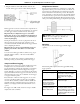
2. Plug the small end of the USB interface cable into the
bottom of the logger as shown in the following diagram.
If the logger has never been connected to the computer before,
it may take a few seconds for the new hardware to be detected.
Use the logger software to launch and read out the logger.
Important: If you configure the logger to start with a
button start, be sure to press and hold down the button on
the front of the logger for at least three seconds when you
want to begin logging.
If using an external sensor, be sure to plug it into the side of
the logger before logging begins. Also select the correct
sensor and activate the external channel in the logger software
when configuring the launch.
Important: If you select an external channel, but do not
plug the probe in, false data will be recorded for that
channel.
You can read out the logger while it continues to log, stop it
manually with the software, or let it record data until the
memory is full.
Refer to the software user’s guide for complete details on
launching, reading out, and viewing data from the logger.
Sample and Event Logging
The logger can record two types of data: samples and events.
Samples are the sensor measurements recorded at each
logging interval (for example, the temperature every minute).
Events are independent occurrences triggered by a logger
activity. Examples of events recorded asynchronously during
deployment include when the logger is connected to the host,
when the battery is low, the end of a data file once the logger
is stopped, and button pushes.
Press the button on the front of the logger for one second to
record an event. Both a button up and down event will be
recorded. This is useful if you want to mark the datafile at a
particular point. For example, if the logger is located in an
incubator, you might press the button each time the door is
opened.
The logger stores 64K of data, and can record up to 43,000
samples and events combined.
Using External Sensors
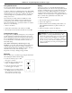
The external input channel has a switched 2.5 V output. This
signal can be used to power a sensor directly or it can also be
used to trigger an external circuit. An external sensor should
draw no more than 4 mA total when powered. The switched
2.5 V output turns on about 15 ms before the external channel
is measured and stays powered for 48 ms after it is measured,
as shown in the following diagram. The striped bar shows the
16 ms period during which the logger samples the input signal.
CAUTION: Analog channel input cannot exceed 2.5
VDC. For sensor outputs up to 10 VDC, use
appropriate voltage adapter cable.
Operation
A light (LED) on the side of the logger confirms logger
operation.
The following table explains when the logger blinks during
logger operation.
When: The light:
The logger is logging
Blinks once every one to four
seconds (the shorter the logging
interval, the faster the light
blinks); blinks when logging a
sample
The logger is awaiting a
start because it was
launched in Start At
Interval, Delayed Start,
or Button Start mode
Blinks once every eight seconds
until launch begins
The button on the logger
is being pushed for a
Button Start launch
Blinks once every second while
pressing the button and then
flashes rapidly once you release
the button. The light then reverts
to a blinking pattern based on the
logging interval
Light
Channel 4
external
input