
User Manual
1-800-LOGGERS 2 www.onsetcomp.com
Specifications (continued)
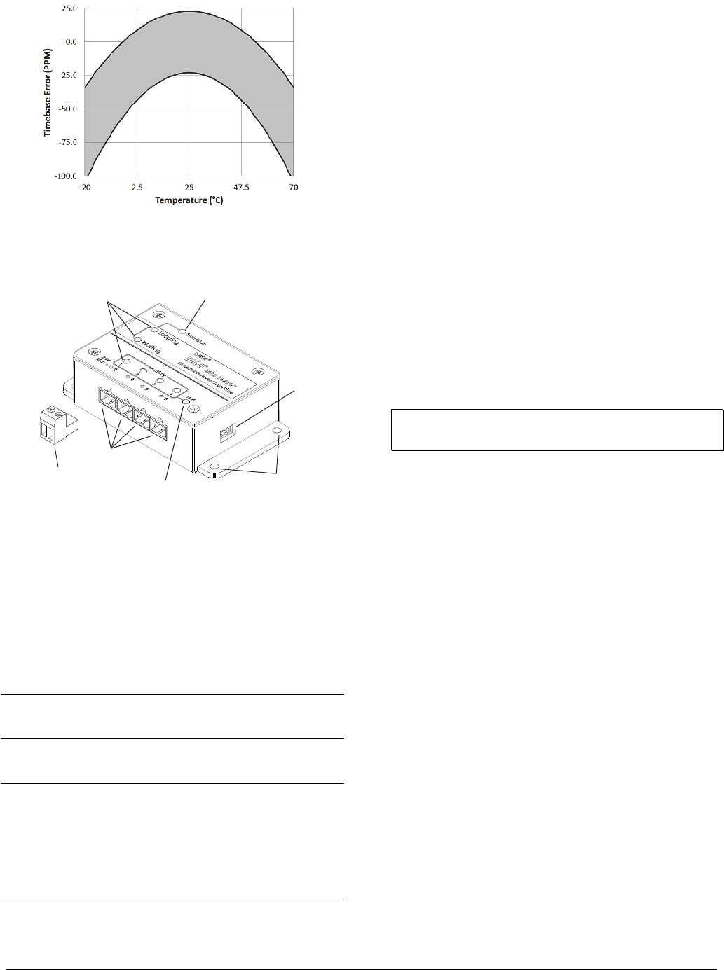
Plot A: Time Accuracy
Logger Components and Operation
Start/Stop Button: Press this button for 3 seconds to start or
stop logging data. This requires configuring the logger in
HOBOware with a Button Start and/or a Button Stop (see
Setting up the Logger). You can also press this button for
1 second to record an internal event (see Recording Internal
Logger Events).
LEDs: There are three types of LEDs on the logger to indicate
logger operation: Logging, Waiting, and Activity. Note that all
LEDs will blink when the logger is initially powered (i.e. when
the batteries are installed).
LED Description
Logging
(green)
Blinks every 2 seconds when the logger is recording data.
Disable this LED by selecting the Turn Off LEDs option in
HOBOware.
Waiting
(orange)
Blinks every 2 seconds when awaiting a start because the
logger was configured with Start At Interval, Delayed
Start, or Button Start settings in HOBOware.
Activity
(red)
There is one Activity LED per input channel. Press the
Test button to activate all four Activity LEDs for 10
minutes to determine the state of the four input
channels. When the logger is recording data, the Activity
LED for the corresponding channel will blink at every
pulse signal. Note: If you press the Test button during
logging, then the Activity LED will remain illuminated for
any channel that has not been configured to record data.
Inputs: There are 4 input channels to connect the logger to
external sensors/devices.
Terminal Blocks: There are 4 terminal blocks included with the
logger to plug into the inputs for connecting devices.
Test Button: Press this button to activate the Activity Lights for
10 minutes to test for contact resistance or voltage signal in any
of the four input channels (see the LED table).
Mounting Holes: There are four mounting holes, two on each
side, that you can use to mount the logger to a surface (see
Mounting the Logger).
USB Port: This is the port used to connect the logger to the
computer or the HOBO U-Shuttle via USB cable (see Setting up
the Logger and Reading Out the Logger).
Setting Up the Logger
Use HOBOware Pro to set up the logger, including selecting the
start and stop logging options, configuring the input channels
for specific sensor types, and entering scaling factors. It may be
helpful to set up the logger with a Delayed Start or a Button
Start first and then bring it to the location where you will
mount it to connect the external sensors/devices and test the
connections before logging begins.
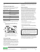
1. Connect the logger and open the Launch window. To
connect the logger to a computer, plug the small end of the
USB cable into the side of the logger and the large end into a
USB port on the computer. Click the Launch icon on the
HOBOware toolbar or select Launch from the Device menu.
Important: USB specifications do not guarantee operation
outside this range of 0°C (32°F) to 50°C (122°F).
2. Select Sensor Type. Each of the input channels can be
configured to log the following:
• Pulse. This records the number of pulse signals per logging
interval (the logger records a pulse signal when the input
transitions to the logic low). There are built-in scaling
factors you can select for supported devices and sensors,
or you can set your own scaling when you select raw pulse
counts. You can also adjust the maximum pulse frequency
and lockout time as necessary.
• State. This records how long an event lasts by storing the
date and time when the state of the signal or switch
changes (logic state high to low or low to high). The logger
checks every second for a state change, but will only
record a time-stamped value when the state change
occurs. One state change to the next represents the event
duration.
• Event. This records the date and time when a connected
relay switch or logic low transition occurs (the logger
records an event when the input transitions to the logic
low). This is useful if you need to know when an event
occurred, but do not need to know the duration of the
event. You can also adjust the lockout time to debounce
switches.
• Runtime.
This records the number of state changes that
happen over a period of time. The logger checks the state
of the line once a second. At the end of each logging
interval, the logger records how many seconds the line
was in the logic low state.
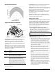
LEDs
Start/Stop Button
USB Port
Inputs
One of Four
Terminal Blocks
Test Button
Mounting Holes